20 5756B
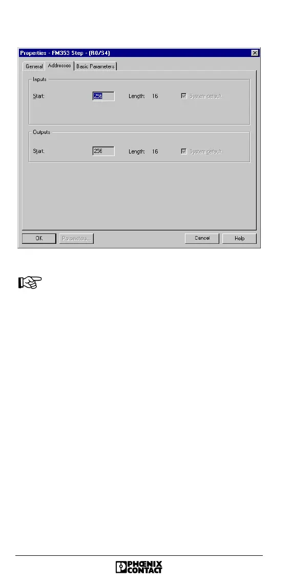
Figure 18 "Properties... Addresses" tab
The controller board occupies 16 byte inputs and
16 byte outputs in the analog PLC area starting from
the base address. The INTERBUS standard registers
are located in this area (see also "Position of the
INTERBUS Standard Registers" on page 43).
For further controller board settings, please refer to "Startup
With IBS CMD SWT G4 Configuration Software" on page 27
(e.g., setting the operating mode, assigning addresses).