64 5756B
Remote Bus Connector With Screw-Clamp Connection
Designation: SUBCON 9/M-SH, Order No. 27 61 50 9
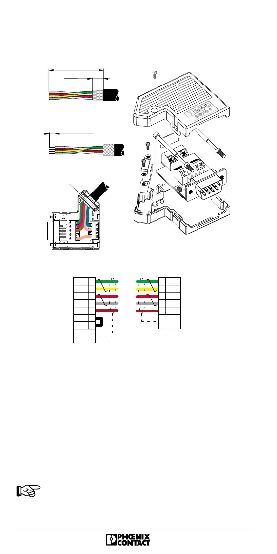
Figure 45 SUBCON connector cabling
1. Strip 50 mm off the cable sheath, and shorten the braided
shield to 10 mm.
Strip 5 mm off the wire ends, and connect the signal lines
in accordance with the drawing.
2. Fold the braided shield back over the cable sheath.
3. Clamp the shield under the strain relief, so that a
conductive connection to the metal-plated connector
housing is created.
Use only the metal-plated connectors recommended
by Phoenix Contact.
9-pos. SUBCON
m ale connector
9-pos. SUBCON
fem ale connector
R e m o te b u s c a b le (S U B C O N 9 /S U B C O N 9 )
G reen
Pink
Yellow
Gray
Brown
DO
DI
COM
6
1
7
2
3
DI
DO
Strain
re lie f
9
6
1
7
2
3
5
DO
DI
COM
DI
DO
Strain
re lie f
1
2
3
Strain relief
5 4 3 2 1
9 8 7 6
5 0 m m (1 .9 7 in .)
10 m m
(0 .3 9 in .)
5 m m (0.20 in.)
5469A036