RAD-...-IFS
88 / 198
PHOENIX CONTACT 105542_en_05
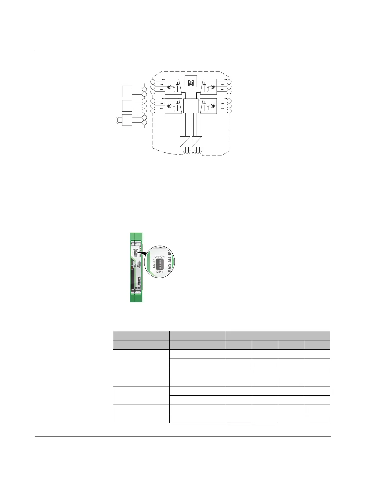
7.1.2 Basic circuit diagram
Figure 7-2 Basic circuit diagram for the RAD-AI4-IFS
7.1.3 Setting the DIP switches
You can configure the input signals using the DIP switches on the front (0 mA ... 20 mA or
4 mA ... 20 mA). Any changes to the DIP switch settings will be applied immediately. In
PLC / Modbus/RTU mode, the setting of the input signals is evaluated for error diagnostics.
When set to 4 mA ... 20 mA, for example, it is possible to detect an open circuit.
Figure 7-3 DIP switches of the RAD-AI4-IFS
Table 7-1 DIP switches of the RAD-AI4-IFS
DIP switch
Setting Input signal 1 2 3 4
Analog IN1
0 mA ... 20 mA OFF
4 mA ... 20 mA ON
Analog IN2
0 mA ... 20 mA OFF
4 mA ... 20 mA ON
Analog IN3
0 mA ... 20 mA OFF
4mA...20mA ON
Analog IN4
0 mA ... 20 mA OFF
4mA...20mA ON
3 Wire
PWR IN
Out
GND
2.1
2.2
2.3
2 Wire
PWR IN
Out
2.1
2.2
4 Wire
Out
GND
U
S
2.2
2.3
IO-MAP
µC
DC
DC
IFS
IFS
3.1
3.2
3.3
I
V
LOOP
PWR
2
+I
2
-I
2
4.1
4.2
4.3
V
LOOP
PWR
3
+I
3
-I
3
I
2.1
2.2
2.3
V
LOOP
PWR
1
+I
1
-I
1
I
5.1
5.2
5.3
V
LOOP
PWR
4
+I
4
-I
4
I
-I4+I4PWR4
-I3+I3PWR3
-I2+I2PWR2
-I1+I1PWR1
OFF ON
DIP-1
1
2
3
4
PWR
DAT
ERR
44
3WR3
22
1WR1
 Loading...