RAD-...-IFS
94 / 198
PHOENIX CONTACT 105542_en_05
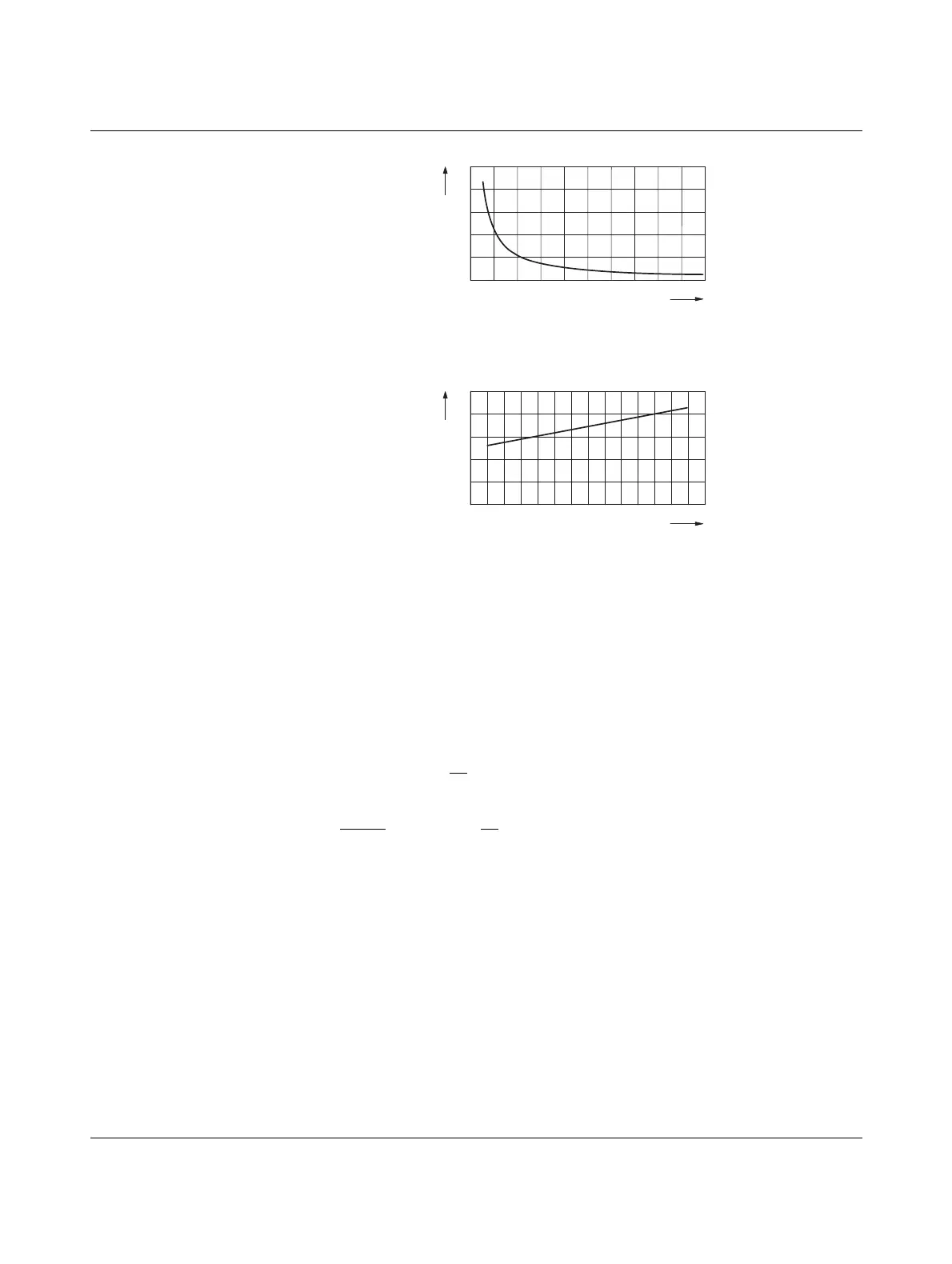
Figure 7-9 Systematic temperature measuring error ΔT depending on cable cross sec-
tion A
Figure 7-10 Systematic temperature measuring error ΔT depending on cable tempera-
ture T
A
(Measuring error valid for: copper cable χ = 57 m/Ωmm
2
, T
A
= 25°C, and Pt100 sensor)
Make sure that the cable resistance and therefore the measuring error is as low as possible:
• Use sensor cables that are as short as possible.
• Avoid cable cross sections smaller than 0.5 mm
2
.
The temperature has only a small influence on the cable resistance.
You can calculate the cable resistance as follows:
Since there are two cable resistances in the measuring system, the value must be doubled.
Using the average temperature coefficient α =0.385Ω/K for Pt100, the absolute measuring
error in Kelvin can be determined for platinum sensors according to DIN.
R
L
= R
L20
x [1 + 0.0039
1
x (T
A
- 20°C)]
K
R
L
=
l
x [1 + 0.0039
1
x (T
A
- 20°C)]
χ x A K
R
L
Cable resistance in Ω
R
L20
Cable resistance at 20°C in Ω
l Cable length in m
χ Specific resistance of copper in m/Ωmm
2
A Cable cross section in mm
2
0.0039 1/K Temperature coefficient for copper (degree of purity of 99.99%)
T
A
Ambient temperature (cable temperature) in °C
0 0,1 0,2 0,3 0,4 0,5 0,6 0,7 0,8 0,9 1,0
0
2
4
6
8
10
T [K]
A [mm ]
2
-50 -30 -10 10 30 50 70 90
0
0,5
1
1,5
2
2,5
T [K]
T [°C]
 Loading...