Description of I/O extension modules
105542_en_05 PHOENIX CONTACT 95 / 198
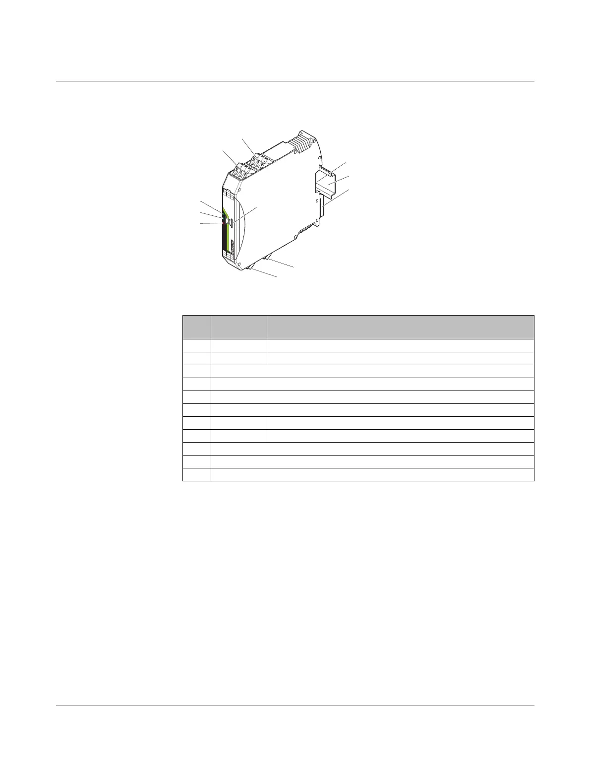
7.2.3 Structure
Figure 7-11 RAD-PT100-4-IFS structure
Item Ter mi na l
block
Designation
1 3.1/3.2/3.3 Pt100 input 2 for 2 and 3-wire sensors
2 2.1/2.2/2.3 Pt100 input 1 for 2 and 3-wire sensors
3 White thumbwheel for setting the I/O MAP address
4 Connection option for DIN rail connector
5DIN rail
6 Metal foot catch for DIN rail fixing
7 4.1/4.2/4.3 Pt100 input 3 for 2 and 3-wire sensors
8 5.1/5.2/5.3 Pt100 input 4 for 2 and 3-wire sensors
9 ERR status LED, red (communication error)
10 DAT status LED, green (bus communication)
11 PWR status LED, green (supply voltage)
IO-MAP
RAD-PT100-4-IFS
PW
R
DA
T
ER
R
8
8
+I
1
+I
2
-U
1
-U
2
-I
1
-I
2
I
3
I
4
-U
3
-U
4
-I
3
-I
4
+I
1
+I
2
-U
1
-U
2
-I
1
-I
2
1
2
3
4
6
8
11
10
9
7
5

 Loading...