Description of I/O extension modules
105542_en_05 PHOENIX CONTACT 99 / 198
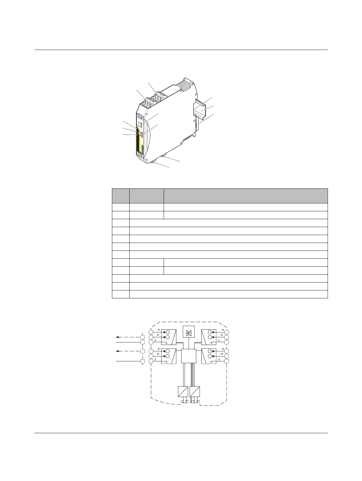
7.3.1 Structure
Figure 7-14 RAD-AO4-IFS structure
7.3.2 Basic circuit diagram
Figure 7-15 Basic circuit diagram for the RAD-AO4-IFS
Item Ter mi na l
block
Designation
1 3.1/3.2/3.3 Analog output 2 (either current or voltage)
2 2.1/2.2/2.3 Analog output 1 (either current or voltage)
3 DIP switches for configuring the outputs (current/voltage output)
4 White thumbwheel for setting the I/O MAP address
5 Connection option for DIN rail connector
6DIN rail
7 Metal foot catch for DIN rail fixing
8 4.1/4.2/4.3 Analog output 3 (either current or voltage)
9 5.1/5.2/5.3 Analog output 4 (either current or voltage)
10 ERR status LED, red (communication error)
11 DAT status LED, green (bus communication)
12 PWR status LED, green (supply voltage)
U
3
IO-MAP
RAD-AO4-IFS
3
4
PW
R
D
AT
ER
R
1
2
3
4
OF
F
ON
DIP-1
8
8
U
4
I
3
I
4
U
1
1
2
U
2
I
1
I
2
U
1
1
2
U
2
I
1
I
2
1
2
3
4
5
7
9
12
11
10
8
6
IO-MAP
µC
DC
DC
IFS
IFS
4.1
U
4.2
I
4.3
U
4
I
4
4
5.1
U
5.2
I
5.3
U
3
I
3
3
3.1
U
3.2
I
3.3
U
2
I
2
2
2.1
U
2.2
I
2.3
U
1
I
1
1
3.2
3.3
GND
2.1
2.3
GND
0...10V DC
0/4...20 mA
 Loading...