Specification Desc./Quantity
Protected circuits: battery-powered, electronic top-box
provision, accessory provision.
5 Fuse 5 Capacity: 5A
Protected circuits: power supply under starter switch,
lights relay, "Keyless" system control unit, ABS control
unit, engine control unit, injection loads relay, tip over
sensor.
6 Fuse 6 Capacity: 5A
Protected circuits: power supply under starter switch,
instrument cluster, stop buttons, brake lights, front and
rear daylight running lights, starter button, hazard warn-
ing lights device and button (blinker), licence plate light.
7 Fuse 7 Capacity: 5A
Protected circuits: power supply under starter switch,
Headlight switch (passing), USB port, diagnostic socket,
electric top-box provision, accessory provision, "Piaggio
MIA" PMP3 device.
8 Fuse 8 Capacity: 15A
Protected circuits: battery-powered, starter switch,
fuses 5, 6, 7.
9 Fuse 9 Capacity: 25A
Protected circuits: battery-powered, ABS control unit.
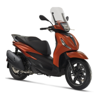
MAIN FUSE
The location and characteristics of the main fuses
on the vehicle are indicated in the table.
For replacement, contact an Authorised Service
Centre.
MAIN FUSE
Specification Desc./Quantity
1 Fuse No. 10 Capacity: 30A
Protected circuits: Vehicle main fuse.
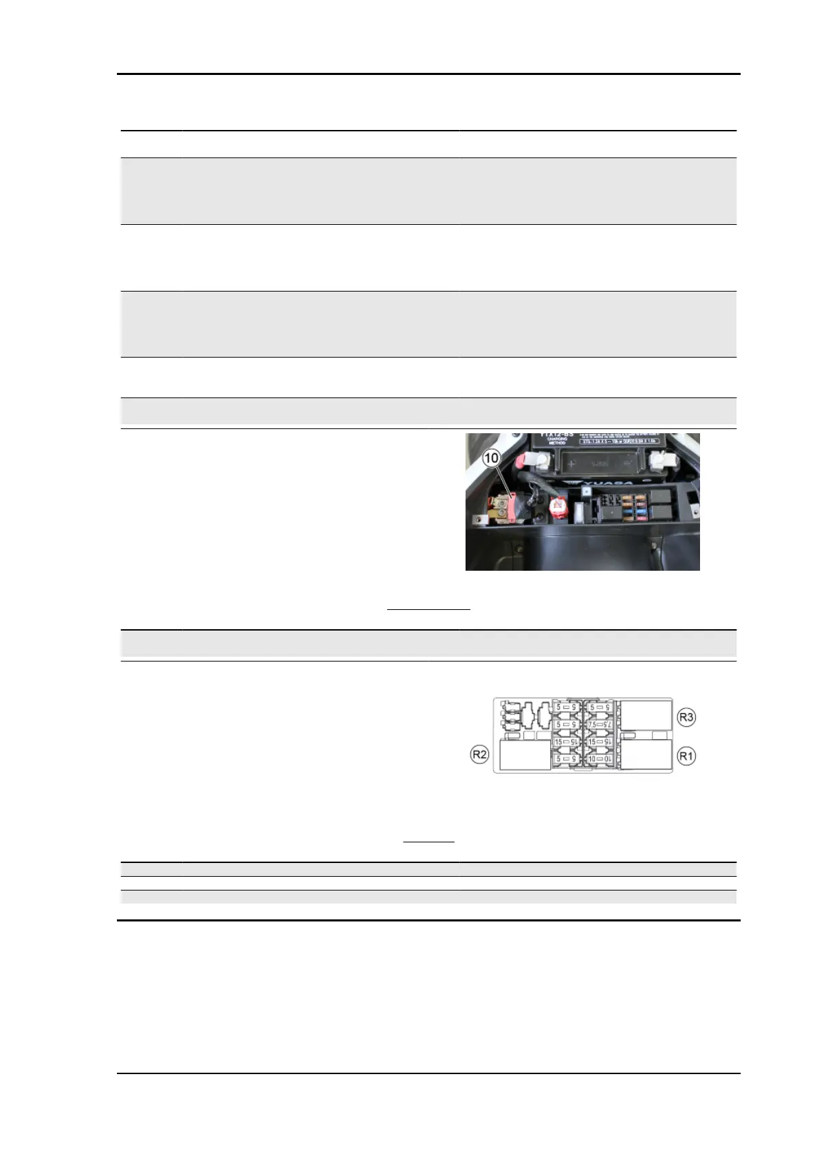
The relays are located in the fuse box under the
saddle.
RELAY
Specification Desc./Quantity
1 Relay no. 1 Circuits: Injection loads.
2 Relay no. 2 Circuits: electric fan.
3 Relay no. 3 Circuits: Lights.
Beverly 400 E5 Electrical system
ELE SYS - 79