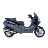
Assemble the limiting bell using the counterweight
fixing screw as a reference.
- Tighten the clamping screw to the prescribed tor-
que.
Locking torques (N*m)
Limiting bell screw 11 ÷ 15 Nm
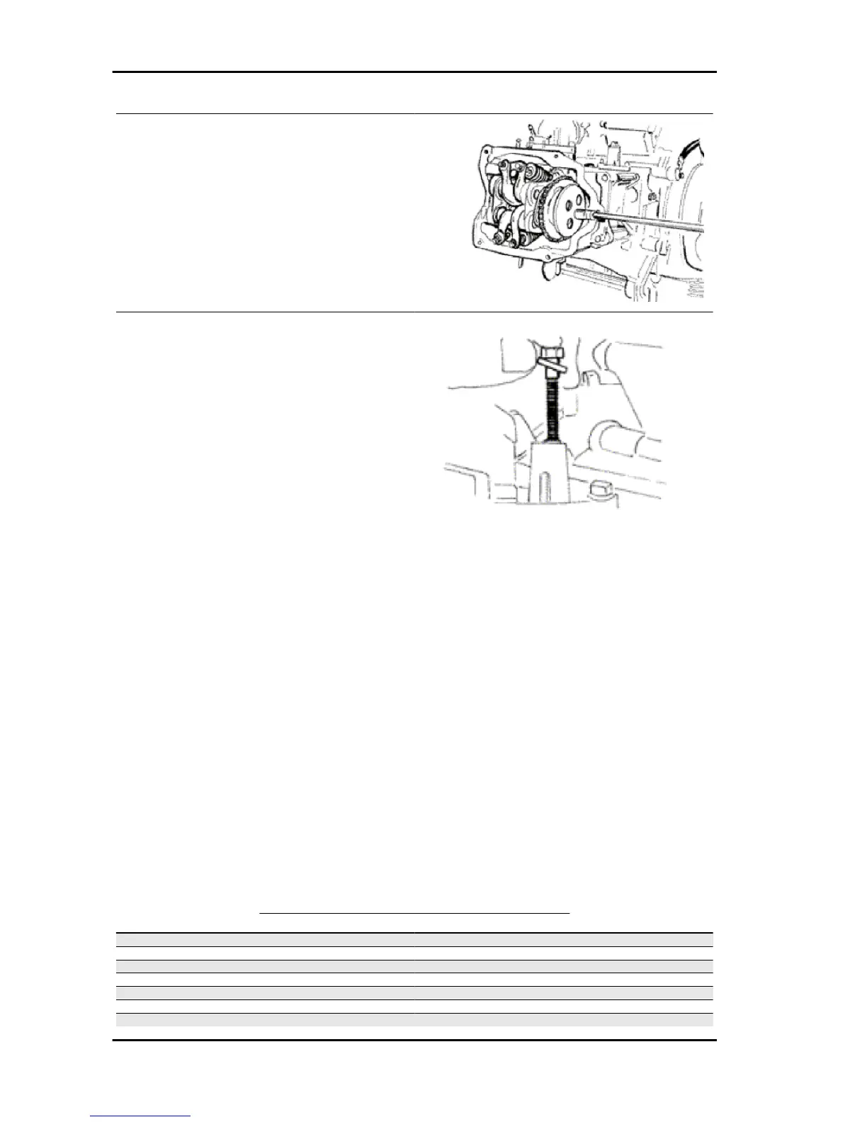
Set the tensioner cursor to the rest position.
- Fit the chain tensioner on the cylinder, using a
new gasket, and tight the two screws to the pre-
scribed torque.
Insert the chain tensioning screw, together with the
spring and washer, tightening it to the prescribed
torque.
Locking torques (N*m)
Tensioner screws 11 ÷ 13 Tensioner cover 5 ÷ 6
Nm
Adjust valve clearance
- Fit the spark plug.
Electrode distance 0.8 mm
Locking torques (N*m)
Spark plug 12 ÷ 14
Refit the cylinder head cover, tightening the 5 screws to the prescribed torque. Make sure the gasket
is positioned properly.
Remove the flywheel cover completely as already described in the flywheel chapter.
- Reassemble the oil pump control, the chain compartment cover, the by-pass and the oil sump as
described in the lubrication chapter.
- Reassemble the driving pulley, the belt and the transmission cover as described in the transmission
chapter.
Locking torques (N*m)
Tappet cover screws 6 - 7 Nm
TIMING SYSTEM COMPONENTS ASSEMBLY
Name
Torque in Nm
Tappet cover screws 6 - 7 Nm
Spark plug 12 ÷ 14
Tensioner cover 5 ÷ 6 Nm
Tensioner screws 11 ÷ 13
Limiting bell screw 11 ÷ 15 Nm
Counterweight screw 7 ÷ 8.5
Plate screws 4 ÷ 6 Nm
Engine Runner 125 - 200
ENG - 170