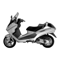
Removal
- Remove the front wheel
- Remove the disk from the front wheel operating
the 6 screws.
Refitting
- Carry out the operations in the reverse order from
the removal being careful to respect the direction
of disc rotation shown by the arrow printed on it
- Tighten the six screws to the specified torque.
Locking torques (N*m)
Brake disc screws: 6 +0.5 -1 Nm
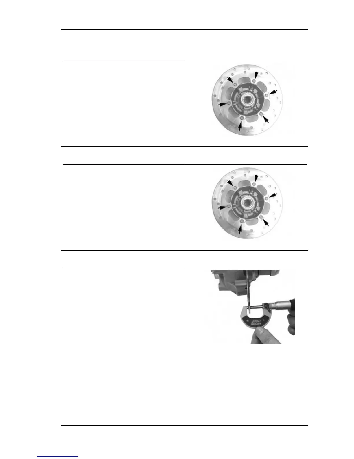
Disc Inspection
- Remove the front wheel
- Use a micrometer to check the disc thickness as
shown in the photograph
- Repeat the measurement in at least 6 points on
the disk
- Remove the front brake calliper
- In order to secure the appropriate tool adequately
use a metal plate with M8 threaded hole and fix it
to one of the two front brake calliper attachment
points
- Place the dial gauge on the disk outer edge
- Make the wheel hub turn and check the disk de-
viation
Specific tooling
020335Y Magnetic support for dial gauge
Runner 125 - 200 Braking system
BRAK SYS - 249