Wiring
System Description Service Robotics Modules
1004870-EN-05
| 86
8 Wiring
8.1 Connections for external devices
An industrial robot that is constructed using service robotics modules from Pilz can be ex-
panded using external devices such as emergency stop pushbuttons, reset buttons, safety
gates etc., depending on the application. The behaviour during a restart can also be con-
figured via the wiring, for example.
The system or plant integrator is tasked with determining the suitable equipment and suit-
able protective measures for the industrial robot depending on the application. Please note
the requirements of any application-dependent circuit diagram (see Circuit
diagram [ 81]).
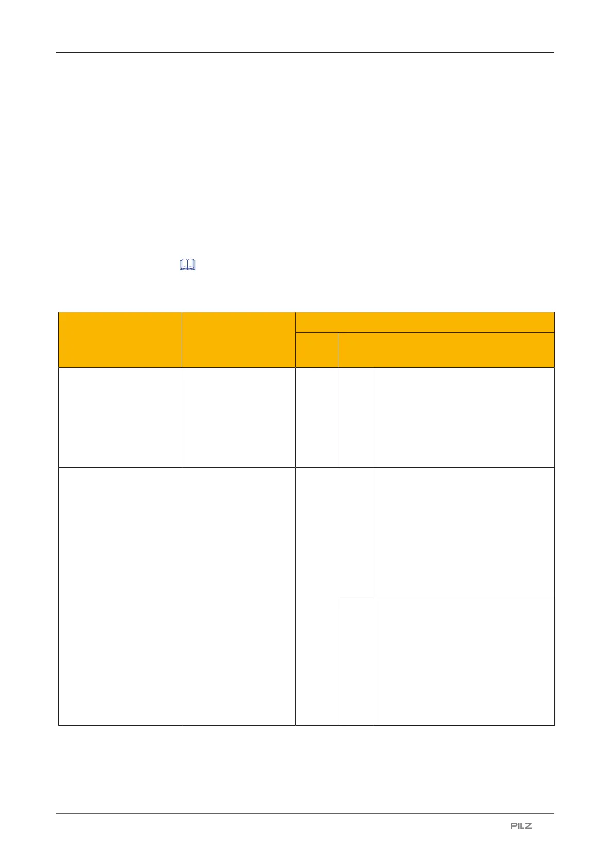
The following FS inputs for connection, prompting, reset and configuration of external
safety devices are pre-prepared:
Device Implementation
(safety control sys-
tem)
Operating manual for robot control module PRCM1
Mod-
ule
Terminal configuration
Reset emergency stop
external
PSSu E F 4DI:
} Digital FS input
} Single-channel
} No test pulse
A1.1 21
} Label in circuit diagram:
Reset emergency stop external OK
} Terminal 21: Input I1
} Terminal 22: +24V periphery supply
} Delivery condition: No external wir-
ing
Emergency stop external PSSu E F 4DI:
} Digital FS input
} Dual-channel
} Test pulse via safety
control system
A1.2 11
} Label in circuit diagram for channel
1:
Emergency stop external channel 1
OK
} Terminal 11: Input I0
} Terminal 12: Test pulse output T0
} Delivery condition: Jumper terminals
11-12
14
} Label in circuit diagram for channel
2:
Emergency stop external channel 2
OK
} Terminal 14: Input I2
} Terminal 13: Test pulse output T1
} Delivery condition: Jumper terminals
13-14

 Loading...


