Overview
System Description Service Robotics Modules
1004870-EN-05
| 14
2.4 Overview of robot control module from Pilz
The robot control module PRCM1 (control cabinet) contains all the components needed to
control the robot arm and any additional equipment depending on the application (e.g. end-
effectors, indicator lights) and to evaluate the signals from any additional equipment de-
pendent on the application (e.g. emergency stop pushbutton, safety gate). The control cab-
inet is equipped with:
} Safety control system from Pilz including
– Pre-installed PSS4000 user program
– Digital FS and ST inputs
– Digital FS outputs
} Motion controller from Pilz including
– Pre-installed motion control user program
– Communication interface (CANopen) for controlling the axes and the end-effector
– Communication interface (Ethernet) for transmitting the robot program from the teach
pendant to the motion controller
} Low voltage power supply (24 VDC)
} Control cabinet main switch
All of the industrial robot's service robotics modules can be switched to a de-energised
state via the control cabinet main switch. The switch position for "de-energised state" is
lockable.
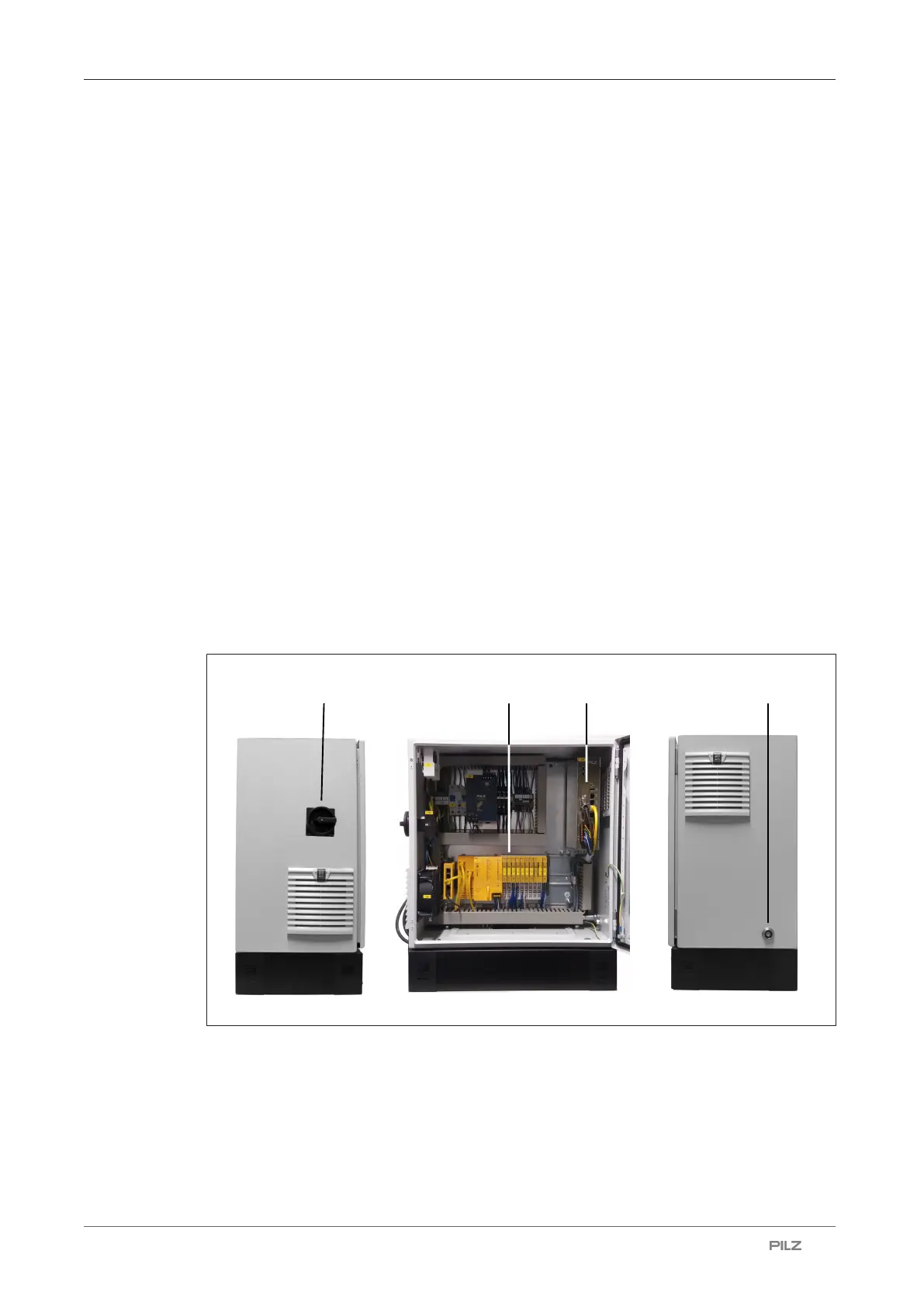
Fig.: Elements and components of the robot control module (control cabinet)
Legend
[1] Control cabinet main switch
[2] Safety control system from the automation system PSS4000
[3] Motion controller
[4] Connection for the teach pendant connection cable or
connection for the bridging plug

 Loading...


