PDP-507CMX
162
1234
1234
C
D
F
A
B
E
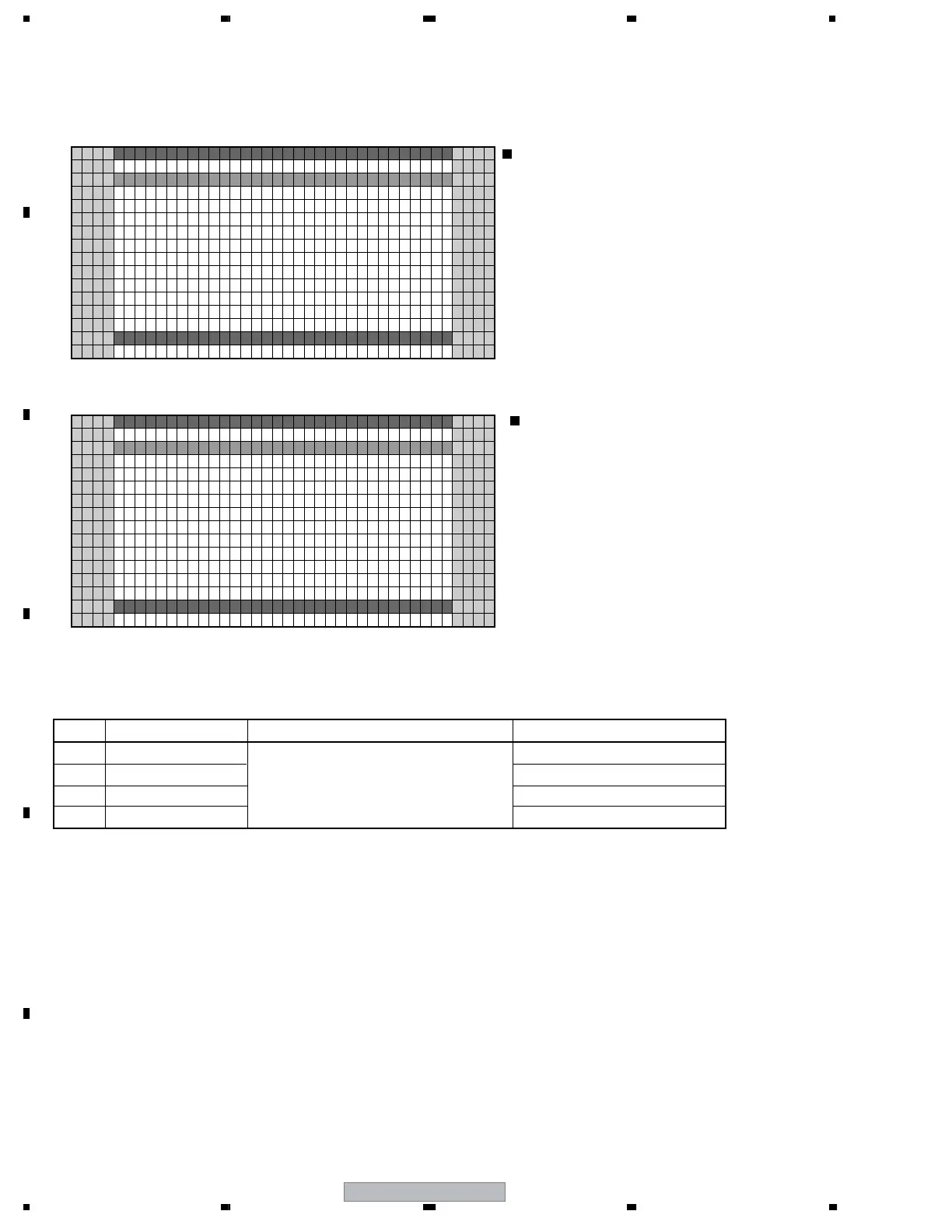
8.4.10 PATTERN MASK SETUP (+)
L/1
[
BT60VS
]
AMSKAPTTEN TSE UP )(+
L/1
[
BT60VS
]
T0PN SMA K 1
AMSK TSE UP
0:6 V
A.PNEL FACT
B–SD 3 2060 –DIG HJ–B7
1
5
10
15
16
15 10 15 20 25 30 32
A.PNEL FACT
B–SD 3 2060 –DIG HJ–B7
1
5
10
15
16
15 10 15 20 25 30 32
APTTEN
<DOWN> : Shifting to COMBI MASK SETUP (+)
<UP> : Shifting to RASTER MASK SETUP
(+)
<SET> : Shifting to the next nested layer
Key operation
<Lower-layer items of PATTERN MASK SETUP (+) >
• The MASK indication sequence can be changed among 48V, 50V, 60V, 72V, 75V, 60P, and 70P, using the Right or
Left key. The selected sequence and the ABL/WB table are retained until the mask is turned off.
• 48V and 60P are represented by 50V and 60V, respectively. The ABL/WB table is changed to the PC table.
No. Items Adjustment/Setting Value RS-232C Command
1 MASK OFF MKS+S00
2 RST MASK 01 <=>
<=> 48V <=> 50V <=> 60V <=> 60P
<=> 70P <=> 72V <=> 75V <=>
(Each sequence can be selected.)
MKS+S01
3• • • • • •
4 RST MASK 39 <=> MKS+S39
<DOWN> : Shifting to the next MASK
<UP> : Shifting to the previous MASK
<RIGHT> : Changing MASK sequence (+)
<LEFT> : Changing MASK sequence (-)
<SET> : Determining the setting value
and shifting to the upper layer
Key operation
• Setting of PATTERN MASK and setting of drive sequence during Pattern Mask mode can be made.

 Loading...