PIPER CHEROKEE SIX SERVICE MANUAL
TABLE VII-I. PROPELLER SPECIFICATIONS
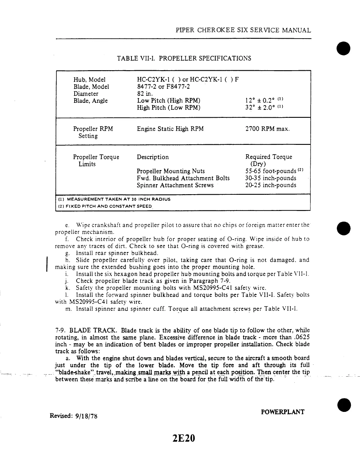
TABLE VII-I. PROPELLER SPECIFICATIONS
Hub, Model
Blade, Model
Diameter
Blade, Angle
Propeller RPM
Setting
Propeller Torque
Limits
HC-C2YK-1 (
) or HC-C2YK-1
( ) F
8477-2 or F8477-2
82 in.
Low Pitch (High RPM)
High Pitch (Low RPM)
Engine Static High RPM
Description
Propeller Mounting Nuts
Fwd. Bulkhead Attachment Bolts
Spinner Attachment Screws
12
± 0.2
°
32° ± 2.0
°
(1)
2700 RPM max.
Required Torque
(Dry)
55-65 foot-pounds (2)
30-35 inch-pounds
20-25 inch-pounds
(1)
MEASUREMENT TAKEN
AT 30 INCH RADIUS
(2) FIXED PITCH AND CONSTANT SPEED
e. Wipe crankshaft
and propeller pilot
to assure that
no chips or foreign
matter enter the
propeller mechanism.
f. Check interior
of propeller hub for proper seating
of O-ring. Wipe inside of hub to
remove any traces
of dirt. Check to see that O-ring
is covered with grease.
g.
Install rear
spinner bulkhead.
h. Slide
propeller
carefully
over
pilot, taking
care
that O-ring
is not
damaged.
and
making sure
the extended bushing goes
into the proper mounting hole.
i. Install the six hexagon head propeller
hub mounting bolts and torque
per Table VII-I.
j. Check propeller blade
track as given in Paragraph
7-9.
k. Safety the propeller
mounting bolts with
MS20995-C41 safety wire.
1. Install the forward
spinner bulkhead and torque bolts
per Table VII-I. Safety bolts
with MS20995-C41 safety wire.
m. Install spinner and spinner cuff. Torque all attachment screws per Table VII-I.
7-9. BLADE TRACK. Blade track is the ability of one blade tip to follow the other, while
rotating,
in almost the same
plane. Excessive
difference in blade
track - more than
.0625
inch - may be an indication of bent
blades or improper propeller installation.
Check blade
track as follows:
a. With the engine shut down and blades vertical, secure to the aircraft a smooth board
just under the tip of the lower blade. Move the tip fore and aft through its full
"blade-shake" travel, makingsmall marks with a pencil at each position. Then center the tip
between these marks and scribe a line on the board for the full width of the tip.
Revised: 9/18/78
POWERPLANT
Revised: 9/18/78
2E20