ATLAS 12 of 44 User’s Manual
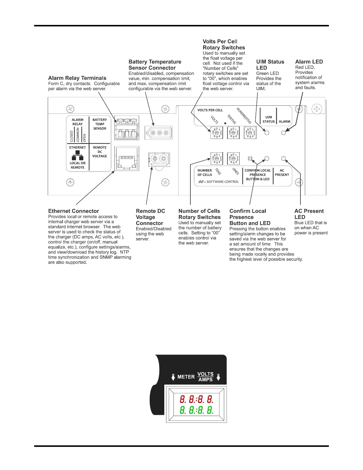
Figure 7-1: User Interface Items on the UIM
7.2. Digital Meter
When the multi-function digital meter option is ordered, it is mounted on the front of the charger. The meter
displays both the charger output voltage and current. The top red number displays the output voltage, which
is measured internal to the charger. Because it is measured internal to the charger, it will differ from the
voltage measured at the battery pack due to the voltage drop of the cabling between the charger and battery
pack. It will also differ from the “Battery Voltage” display ed on the web server “Dashboard” for the same
reason. The bottom green number displays the output current of the charger, so depending on the
application, the battery pack and load may share this current. Figure 7-2 illustrates the digital meter.
Figure 7-2: Optional Digital Meter