ATLAS 31 of 44 User’s Manual
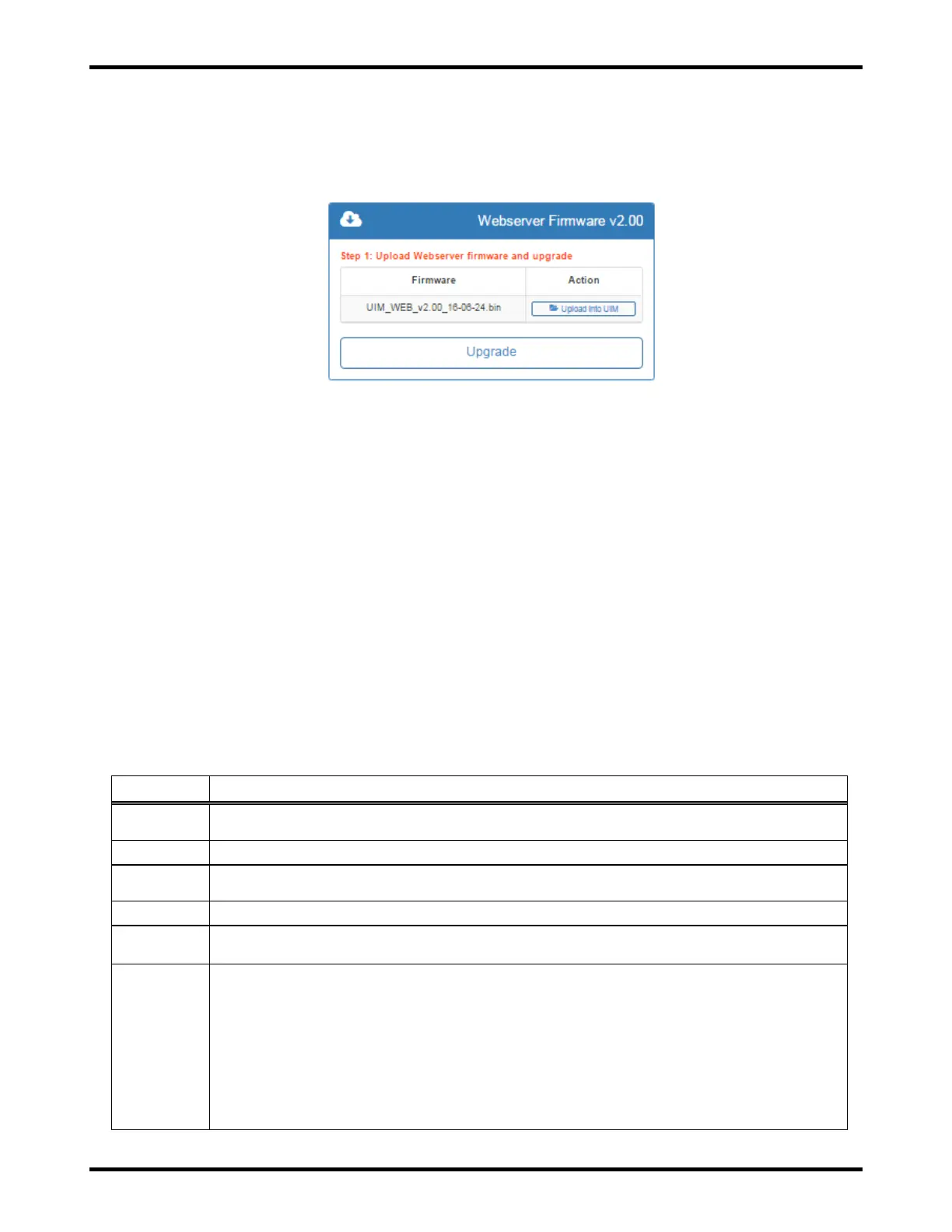
The UIM webserver firmware current version is displayed in the blue box labeled Webserver Firmware vX.XX.
When a new version of code is uploaded to the UIM that version will be displayed to the left of the "Upload to
UIM" box. The Webserver Firmware can be upgraded by (1) selecting a firmware file and uploading it using
the “Upload Into UIM” button and (2) pressing the “Upgrade” button.
Figure 11.9-3: Webserver Firmware Section of the Configuration >> Upgrades Page
11.10. History
On the “History” page, you will currently find the “Alarm E vents” section, whic h is shown in Figure 11.10-1. All
alarms that are enabled on the “Configuration >> Alarm Settings” page (see Section 11.4) will be logged.
Separate records are logged when an alarm becomes Active (triggered) and when an alarm is Cleared.
The “Alarm Events” section includes two (2) sub-sections. The “Most Recent Alarm Records” sub-section
includes a table with the 50 most recent alarm records. These records can be sorted by clicking on the table
headers, searched using the “Search” box, or downloaded as a comma-separated values (CSV) file to be
opened and analyzed in a spreadsheet program/app, such as Microsoft Excel (see Figure 11.10-2 for an
example CSV file).
The “Download All Alarm Records” sub-section allows you to download all available alarm records as a CSV
file. The total number of available records is listed in this sub-section. The charger can store over 10,000
records. When the record storage is full, the oldest 300 records (approximately) will be permanently deleted
in order to make room for new records.
Alarm records include the following fields.
Sequential record ID. The ID resets back to “1” for new records when the record storage
is full and the oldest records have been deleted in order to make room for new records.
The date and time when the alarm was cleared or became active (triggered).
The source of the alarm (“UIM” for the User Interface Module or iPM and slot number for
the intelligent Power Module).
The name of the alarm (for example, “AC Input Power Lost”).
“0” for records where an alarm was cleared.
“1” for records where an alarm became active (triggered).
“Cleared” for records where an alarm was cleared.
“Active” for records where an alarm became active (triggered) for alarms that do not
have a “Trigger Level” associated with them (for example, “AC Input Power Lost”).
For alarms that do have a “Trigger Level” associated with them (for example, “Min DC
Output Current”), the actual val ue at the time that the alarm was triggered is included
in the “Value” field.
iPM fault codes in the value column will have "Active - Code: #" where the # will be
replaced with a number based off the iPM fault code list. Reference the iPM Fault
Code chart in Figure 11.10-3.