8 INSTALLING THE EXPOSURE SWITCH
30 Planmeca ProOne Installation Manual
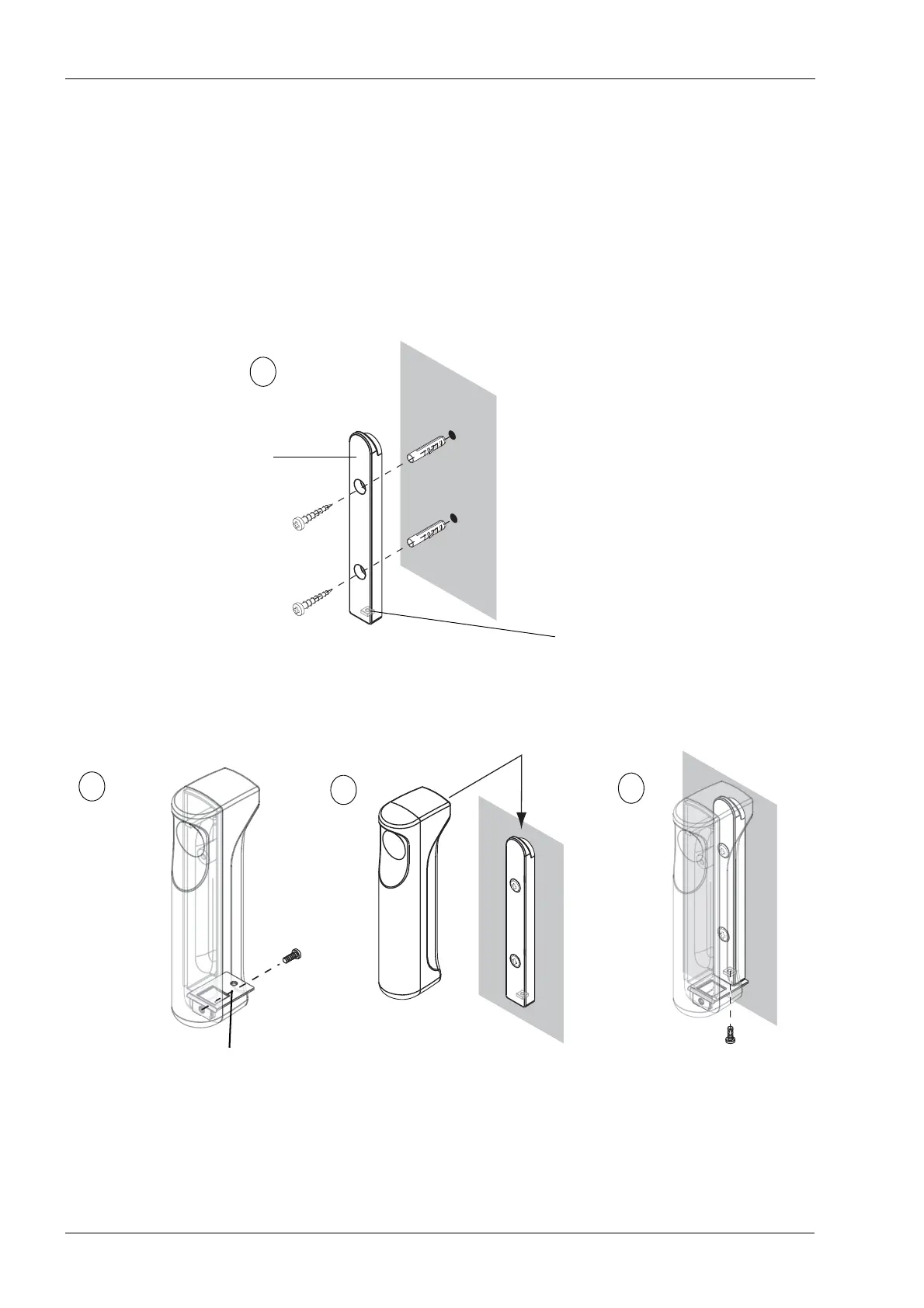
8.2 Stationary exposure switch
Use the holder plate to mark the position of the exposure switch.
• If the wall is made of concrete or brick, use the 4x30 screws and the 6x30
expansion anchors. Drill ø6mm (0.23 in.), 20 mm (0.8 in.) in depth, securing
holes and place the expansion anchors onto the holes.
• If the wall is made of wood, use the 4x30 screws. Do not use the expansion
anchors with wooden wall. Drill ø3 mm (0.11 in.), 20 mm (0.8 in.) in depth, holes
for the attachment screws.
Make sure that the exposure switch attachment nut is in position at the lower end of the
holder plate. Attach the holder plate to the wall with the two attachment screws.
Attach the fastening plate to the exposure switch with an EJOT PT 30x8 WN1451 screw.
The exposure switch can now be positioned on the holder plate. Then attach the exposure
switch to the holder plate with an M3x10 DIN 912 screw.
Connect the exposure switch cable to the terminal on the back of the moving column. To
do this, you will first have to remove the cover that protects the terminals. Remove the
protective cover by unscrewing the two screws at the bottom and then unlatching the
cover at the top.
Exposure switch attachment nut
Holder plate
A