3.60
ENGINE
2. Lightly tighten all fasteners evenly to eliminate any gaps
that may be present in the mounting areas.
3. Torque fasteners to specification using a 2 part sequence.
• Torque fasteners to half of the specified torque value
• Then torque fasteners to the full specified torque value
Install drive clutch, driven clutch, and belt. Torque to
specification (see Chapter 6).
• Clean clutch sheaves thoroughly and inspect inlet and
outlet ducts for proper routing and sealing.
To install engine assembly, reverse the “Engine Removal”
procedure detailed earlier in this Chapter.
• Properly route all electrical harnesses for engine
assembly installation. Check for any possible rubbing
points of electrical wires.
• Carefully set the engine assembly into the vehicle while
installing the propshaft.
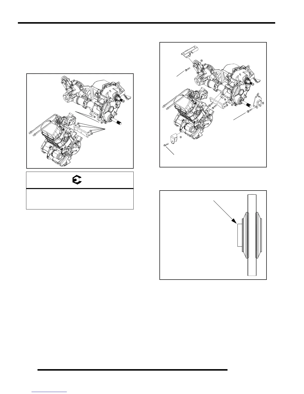
• Install engine / transmission / rear gearcase mounting
hardware and torque to specification.
NOTE: If isolator mounts were removed or replaced,
use the following illustration to ensure proper
orientation during installation.
• Replace exhaust gaskets. Seal connections with high
temp silicone sealant. Check to be sure all exhaust
springs are in good condition.
• Inspect transmission operation and adjust linkage if
necessary (see Chapter 2 “Shift Linkage Adjustment”).
• Checks fluid levels: engine oil, transmission lubricant,
and rear gearcase lubricant.
• Bleed cooling system as described in this Chapter under
“Cooling System Bleeding Procedure.”
= T
Engine / Transmission Mounting Fasteners
(2) Lower 3/8” Nuts: 40 ft. lbs. (54 Nm)
(4) Outer M8 Bolts: 28 ft. lbs. (38 Nm)
40 ft. lbs.
(54 Nm)
28 ft. lbs.
(38 Nm)
17 ft. lbs.
(23 Nm)
17 ft. lbs.
(23 Nm)
30 ft. lbs.
(41 Nm)
The protrusion of the mount
must face inward towards
the engine.
The protrusion of the mount
must face the RH side of
the vehicle.
Front Isolator Mounts
Rear Isolator Mounts
Mount Protrusion
 Loading...