Final Drive / Propulsion
5.16
Pump Assembly / Installation -- Continued
8. Attach steering linkage to steering nozzle. Tighten to
specifications.
9. Attach bilge siphon hose(s) to pump assembly. Use
panduit strap to secure hose(s).
10. Using a grease gun, grease bearing carrier. Reinstall
the coupler shroud. Tighten clamp to 35 in.lbs.
11. Attach reverse gate to reverse linkage with new cotter
pin. Bend ends of cotter pin in opposite directions. If
secured by bolt, tighten to specifications.
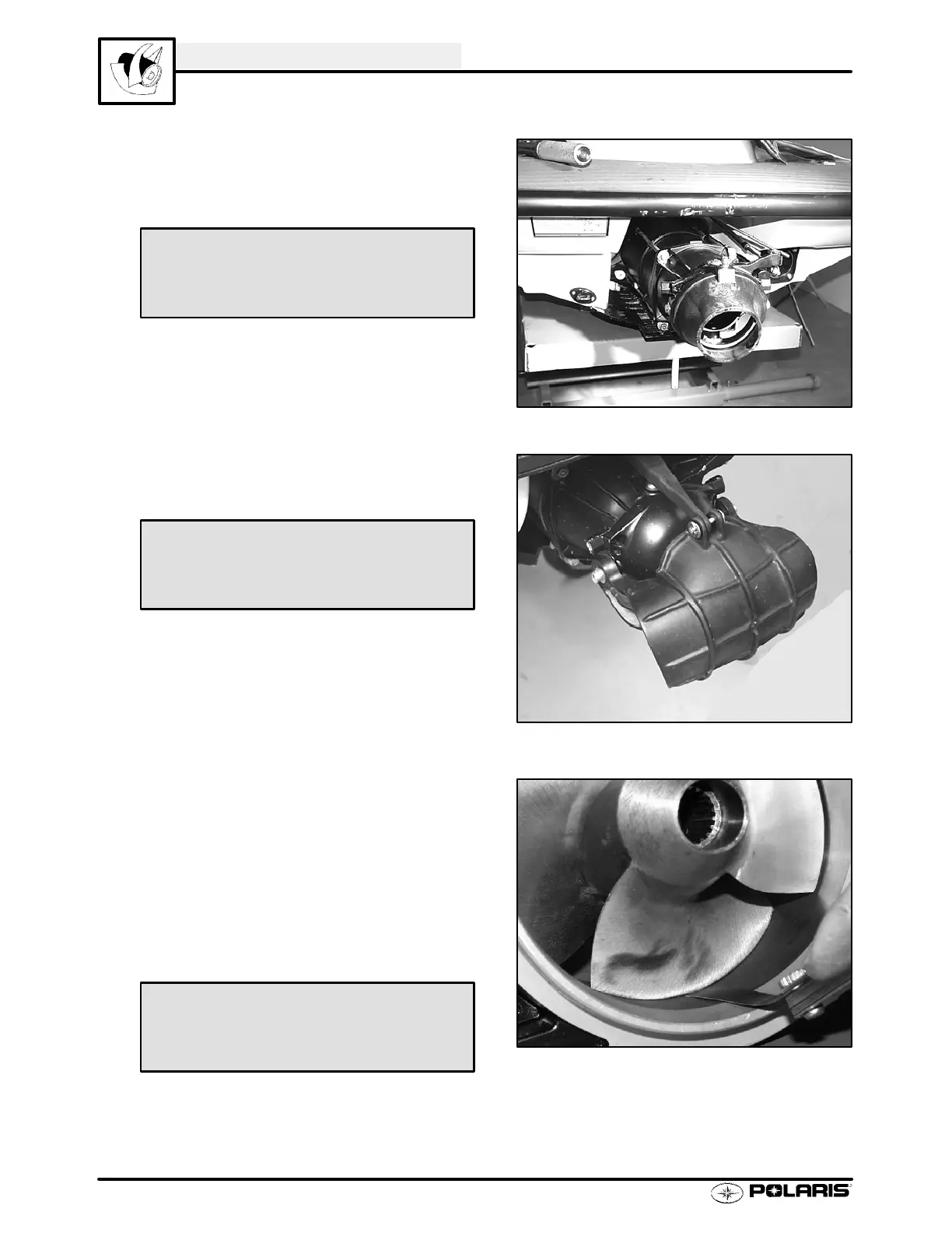
Impeller Clearance
1. Remove lanyard cord and lock plate from engine
stop switch. Disconnect battery ground (--) cable.
2. Remove intake grate and check impeller to housing
clearance with a feeler gauge. Measure clearance
at leading edge, middle, and trailing edge of each
blade. Replace impeller if clearance exceeds
service limit at any point. If clearance exceeds
service limit with a new impeller , replace pump
housing.
Steering Nozzle Bolt Torque
8ft.lbs. (11Nm)
Reverse Nozzle Bolt Torque
14 ft.lbs. (19 Nm)
Impeller Clearance
Std: .002 - .008² (.05 -.20 mm)
Service Limit: .020² (.5 mm)
 Loading...