If the Chiller is equipped with the heater option, a Reservoir vent should be installed. This vent relieves pressure
within the Reservoir as coolant heats and expands.
It may be also necessary to vent and/or add a venting pipe to the Chiller to prevent siphoning and/or overflow
due to the amount of fluid external to the Chiller’s reservoir and/or location of the process being cooled.
NOTE: If the amount of fluid present in the process piping when the Chiller is turned OFF exceeds the
capacity of the Reservoir, it may be necessary to install a normally closed (NO) solenoid valve on the
Chiller’s fluid inlet and a check valve on the Chiller’s fluid outlet to prevent backflow into the unit.
Full Flow Bypass
This allows the operator to adjust the maximum operating pressure to the process. For low pressure pumps, the
pressure range is 7 to 35 psi (0.5 to 2.4 bar). For high pressure pumps, the pressure range is 30 to 100 psi (2.1
to 6.9 bar). The Full Flow Bypass is located on the left front side of the Chiller housing just above the pump.
NOTE: The Full Flow Bypass also protects the pump when running continuously under dead head conditions
caused by a blockage in the process or process lines.
Adjusting the Full Flow Bypass Pressure Setting
WARNING: Hazardous voltages are present.
The pressure setting on the Full Flow Bypass is adjusted as follows:
1. Set the minimum allowable flow rate to 0 (see Normal Operation, Setting Operational Parameters /
Limits, Minimum Flow Rate).
2. Completely block the flow from the Chiller’s fluid outlet. This should cause the pressure to rise.
3. Set the Pressure / Flow Rate Display to read in either PSI or kPa (see Normal Operation, Selecting the
Pressure / Flow Rate Display and Units).
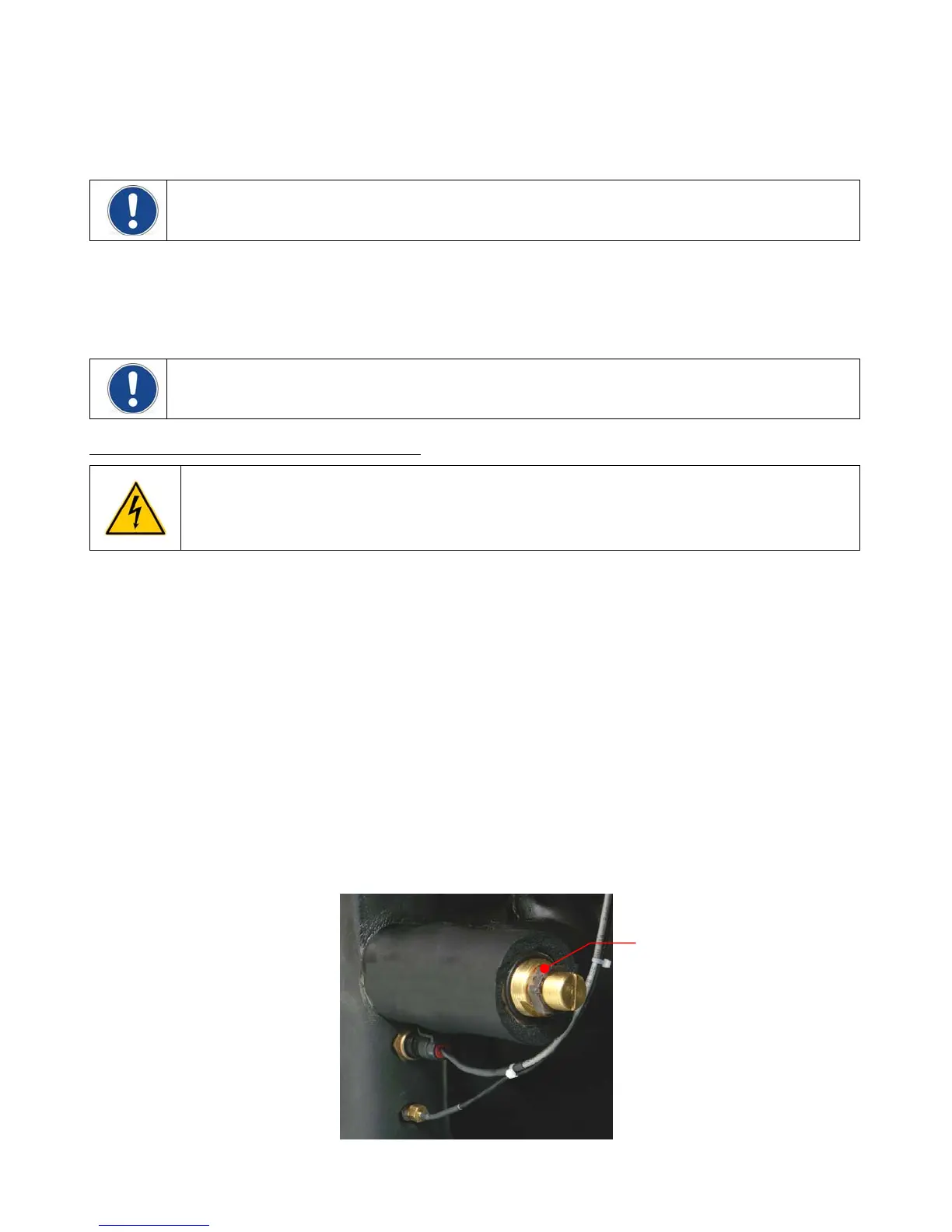
4. Remove the insulation covering the pressure regulating valve cap and then remove the cap. There may
be some coolant in the cap; this is normal.
5. Loosen the locknut and then using a flat blade screwdriver, adjust the pressure until the reading on the
Pressure / Flow Rate Display matches the desired maximum operating pressure. A clockwise rotation
increases pressure; a counter-clockwise rotation decreases pressure.
6. Set the minimum allowable flow rate to the desired value.
7. Tighten the locknut and replace the cap and insulation.
8. Set the Pressure / Flow Rate Display to the preferred reading (GPM, LPM, PSI, kPa).
Locknut
Full Flow Bypass Valve
110-279 17