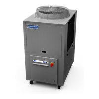
Controls and Components
Your DuraChill Chiller consists of three basic sub-systems:
• Control
• Fluid circulation
• Cooling
This section describes these sub-systems in detail and includes information on the available options. Please
note that your Chiller may or may not be equipped with all the components discussed.
Control System
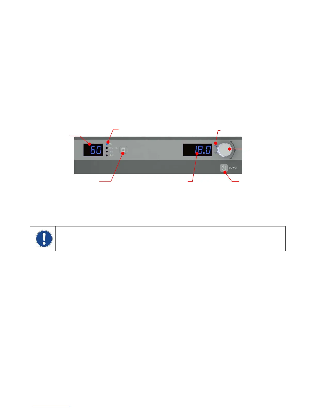
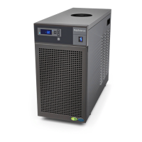
Control Panel — Temperature set point, temperature units, and other operating parameters are set via the
Control Panel. Operating information is displayed on a local digital readout.
Power Switch / Disconnect — The main power switch is located on the front door of the Chiller. This switch
also functions as a power disconnect when access to the unit’s components and terminal blocks is required; the
access door cannot be opened until the Power Switch / Disconnect is placed in the OFF position.
NOTE: Loss of Power – In the event that power is lost while the Chiller is operating, the unit will
automatically resume operation when the power is restored. If the unit was in Standby mode when power is
lost, it will power up in Standby mode. The above is also true if power is removed via the Power Switch /
Disconnect.
Temperature Probe — An internal RTD is used to measure fluid temperature downstream of the pump. Its
reading is displayed on the Control Panel’s LED temperature display.
Flow Sensor — Monitors process fluid flow. If the flow rate is less than the user-settable alarm value, power to
the pump, compressor, and fan is removed and an alarm message displayed on the Control Panel’s LED
readout.
Flow Switch — Requires a minimum of ~4 gpm (15.1 lpm) to close. If the flow rate is too low, the switch will
open and power to the pump, compressor, and fan removed; an alarm message will also be displayed on the
Control Panel’s LED readout.
Fluid Pressure Sensor — Measures fluid pressure at the pump outlet. If the fluid pressure exceeds the user-
settable alarm value, power to the pump, compressor, and fan is removed and an alarm message displayed on
the Control Panel’s LED readout.
Refrigerant Pressure Switches — When activated, these switches remove power to the pump, compressor,
and fan; an alarm message is also displayed on the Control Panel’s LED readout.
The Low Pressure Switch opens if the refrigerant pressure falls below 10 psi (0.7 bar) and closes if the
pressure is above 30 psi (2.1 bar). The Low Pressure Switch will auto-reset.
The High Pressure Switch opens if the refrigerant pressure exceeds 630 psi (43.4 bar). The High
Pressure Switch must be manually reset (see Troubleshooting, Compressor Overload Fault).
Units / Menu
Select Button
Pressure / Flow
Rate Display
Pressure / Flow Rate Unit
Select / Set Knob
Temperature Unit
Temperature
Display
Power Button
110-279 8