3-8
3 First Steps
11 VIDEO
network connection (blue background)
Connection for the blue network cable from the front-end/from the junction box to
transmit the video signal of the video camera in the scanning head
12
USB interfaces (Universal Serial Bus, type A)
Alternative connections for peripheral devices such as mouse, keyboard, etc. or
to connect the hardlock to release the software
13 NETWORK
and
WLAN
network connections
Connection option for an Ethernet network and WLAN router network cable
connection for using of the PSV Commander software
14
Monitor connection (DVI jack)
Not used
15 COM 1
serial interface (9-pin Sub-D plug)
16
Monitor connections (DisplayPort)
Not used
17 KEYBOARD
connection (6-pin circular jack)
Not used
18 MOUSE
connection (6-pin circular jack)
Not used
19
Mains connection (socket for standard power cord)
20 I/O
mains switch
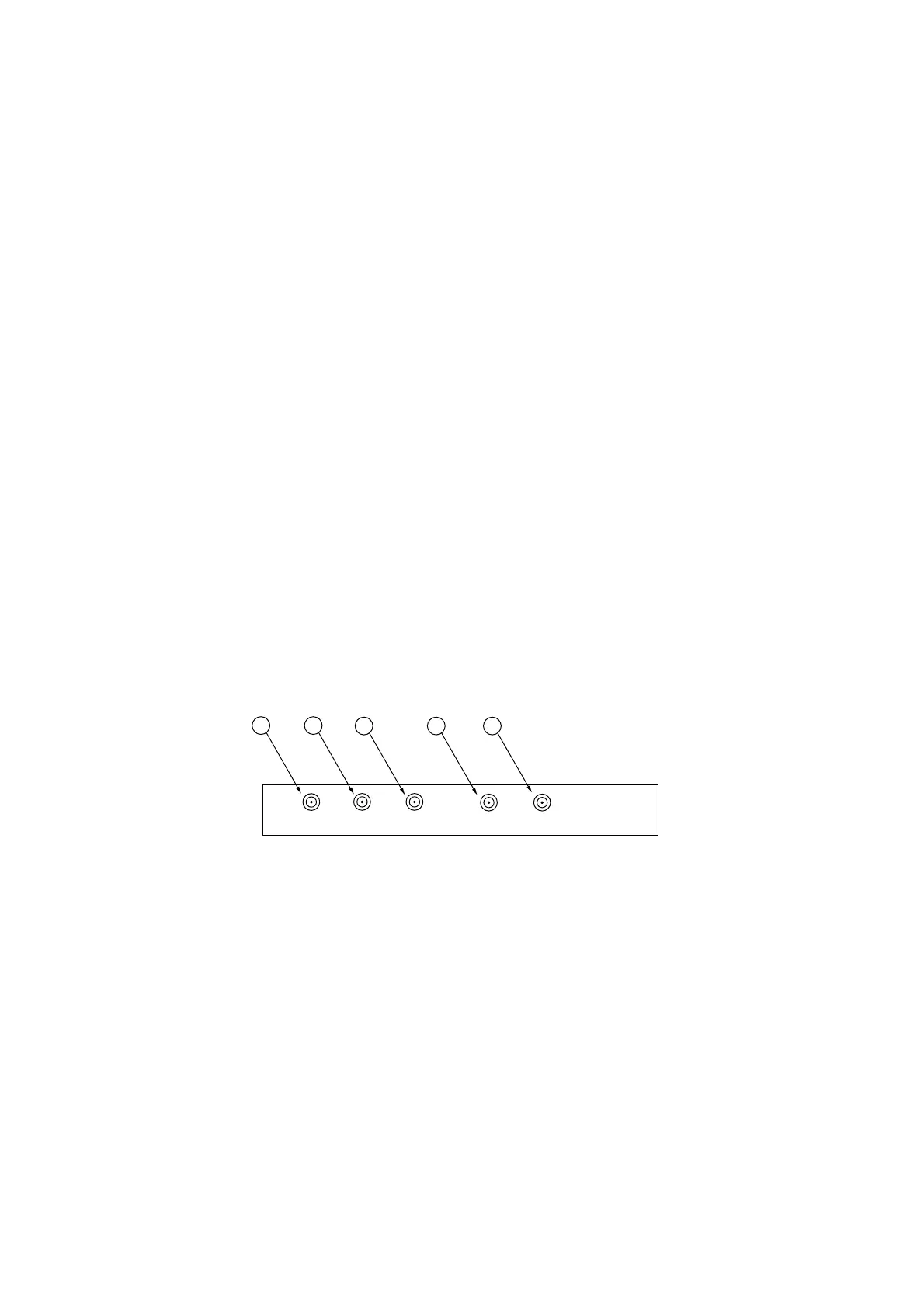
Generator board
The connections of the Spectrum M2i.6030 generator board are shown in the
following figure.
Figure 3.6: View of the generator board
1Ck
clock input (SMB jack)
Input for the clock signal (Clock) to synchronize the generator board with the data
acquisition board
2Trg
signal input (SMB jack)
Input is not used!
3D1
pulse output (SMB jack)
Output is not used!
4D0
pulse output (SMB jack)
Synchronization pulse for the signal of the function generator
5Ch0
signal output (SMB jack)
Signal output of the function generator