3-7
3 First Steps
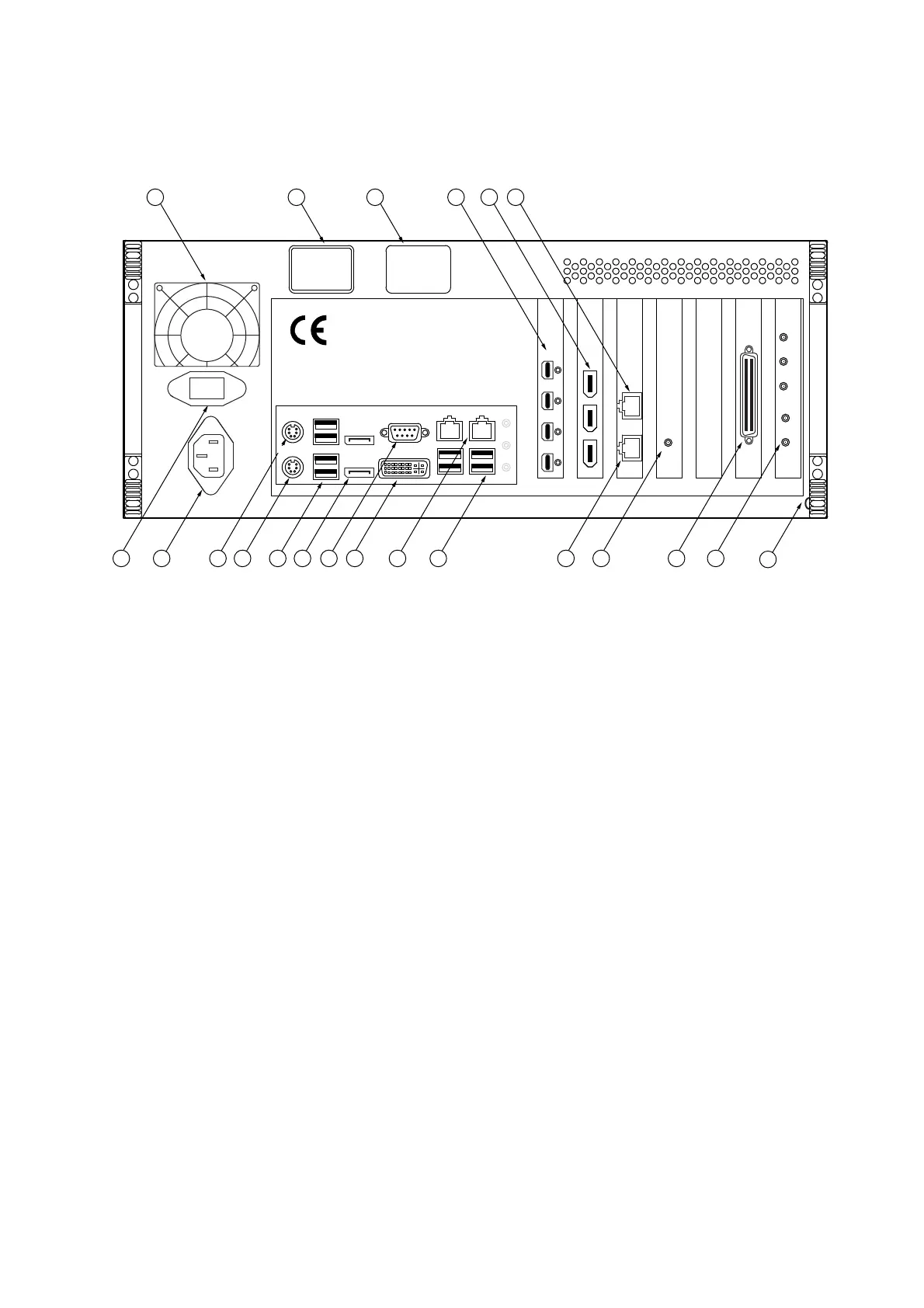
Back view
The back view of the PC is shown in the following figure. The order of the
plug-in boards may vary from that shown in the figure.
Figure 3.5: Back view of the PC
1
Cooling fan
2
Name plate
Plate with information on model, serial number, power specifications, etc.
3
Warning label
4
Monitor connections (Mini DisplayPort)
Connection for the monitor cable to the TFT monitor
5
IEEE-1394 interfaces (FireWire plugs)
6 CONTROL
network connection (yellow background)
Connection for the yellow network cable from the front-end to control the system
via the software and to transmit data
7
Connection for cable shielding (blade connector)
Not used
8 GENERATOR
connections of the generator board (SMB jacks)
Connections for the generator cable to the front-end to transmit the signals of the
function generator. The individual connections of the generator board are
described in detail in the following in the Generator Board section.
9 ACQUISITION
connector (SCSI-II type)
Connection for the Acquisition cable from the front-end to transmit the vibrometer,
trigger, and reference signals
10 CK
connection
Connector for the SMB-SMB connecting cable to synchronize the data acquisition
board with the generator board
12
20 1519 18
17 14
13
12
11
10 8
16
9
KEYBOARD
MOUSE
CONTROLVIDEO
ACQUISITION
Ck
D0
Trg
Ch0
D1
GENERATOR
CK
7
6
5
4
3
2
1
I
O
DP3
DP4
DP2
DP1
NETWORK WLAN