3-7
3 First Steps
Back view
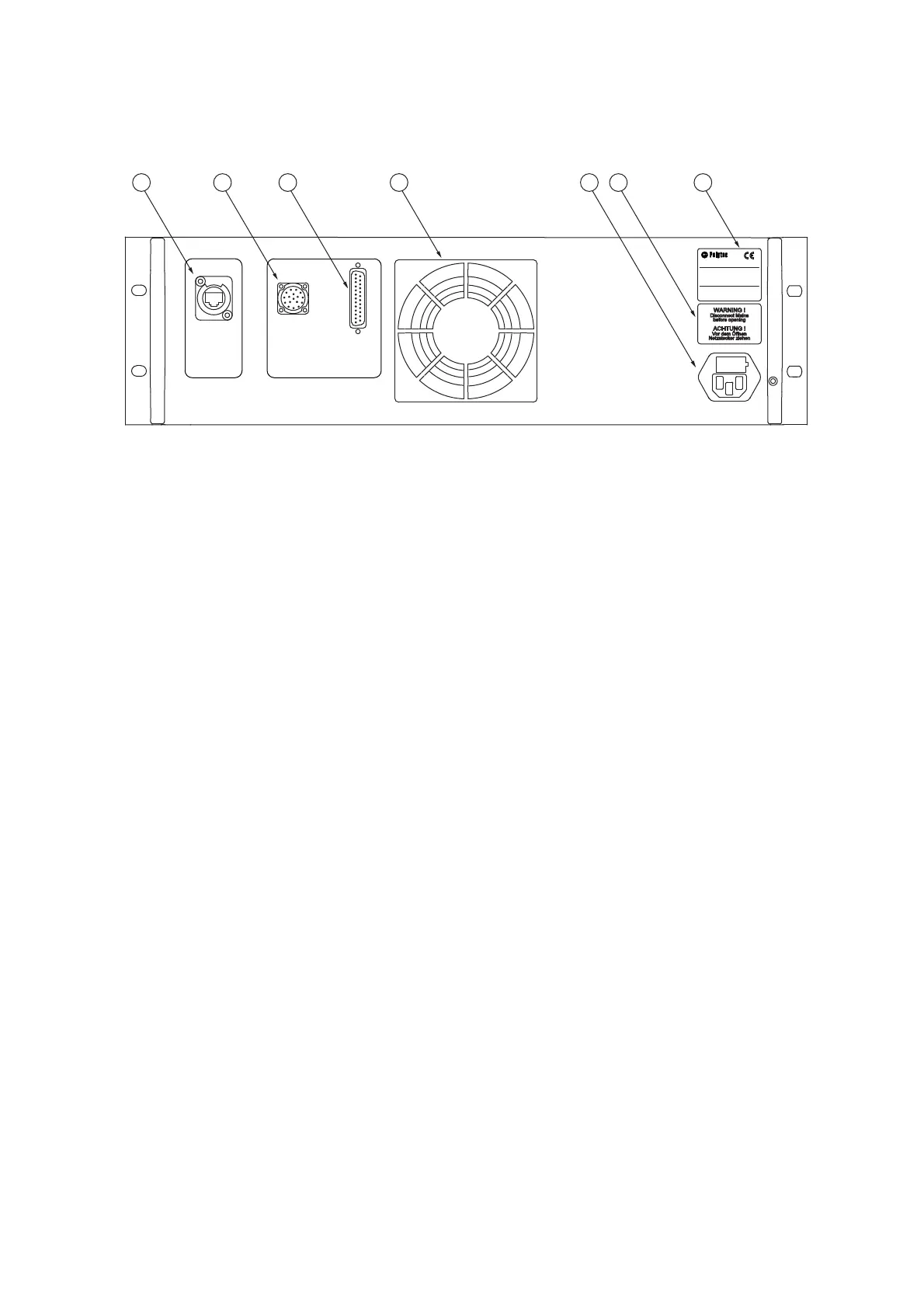
The back view of the controller is shown in the following figure.
Figure 3.5: Back view of the controller
1 ETHERNET
network connection
Connection for the network cable from the industrial PC
2MOTOR
connection (17-pin circular connection)
Connection for the motor cable to the sensor head for the power supply and the
signal transmission of the linear stage motor.
3 CONTROL
connection (25-pin Sub-D jack)
Connection for the control cable to the sensor head for the power supply and the
signal transmission to the sensor head.
4
Cooling fan
5POWER
mains connection (socket for standard power cord with built-in fuses)
6
Warning label
7
Name plate
Plate with information on model, serial number, power specifications etc.