3-3
3 First Steps
3.2 Control Elements, Displays, and Connections
3.2.1 Sensor Head
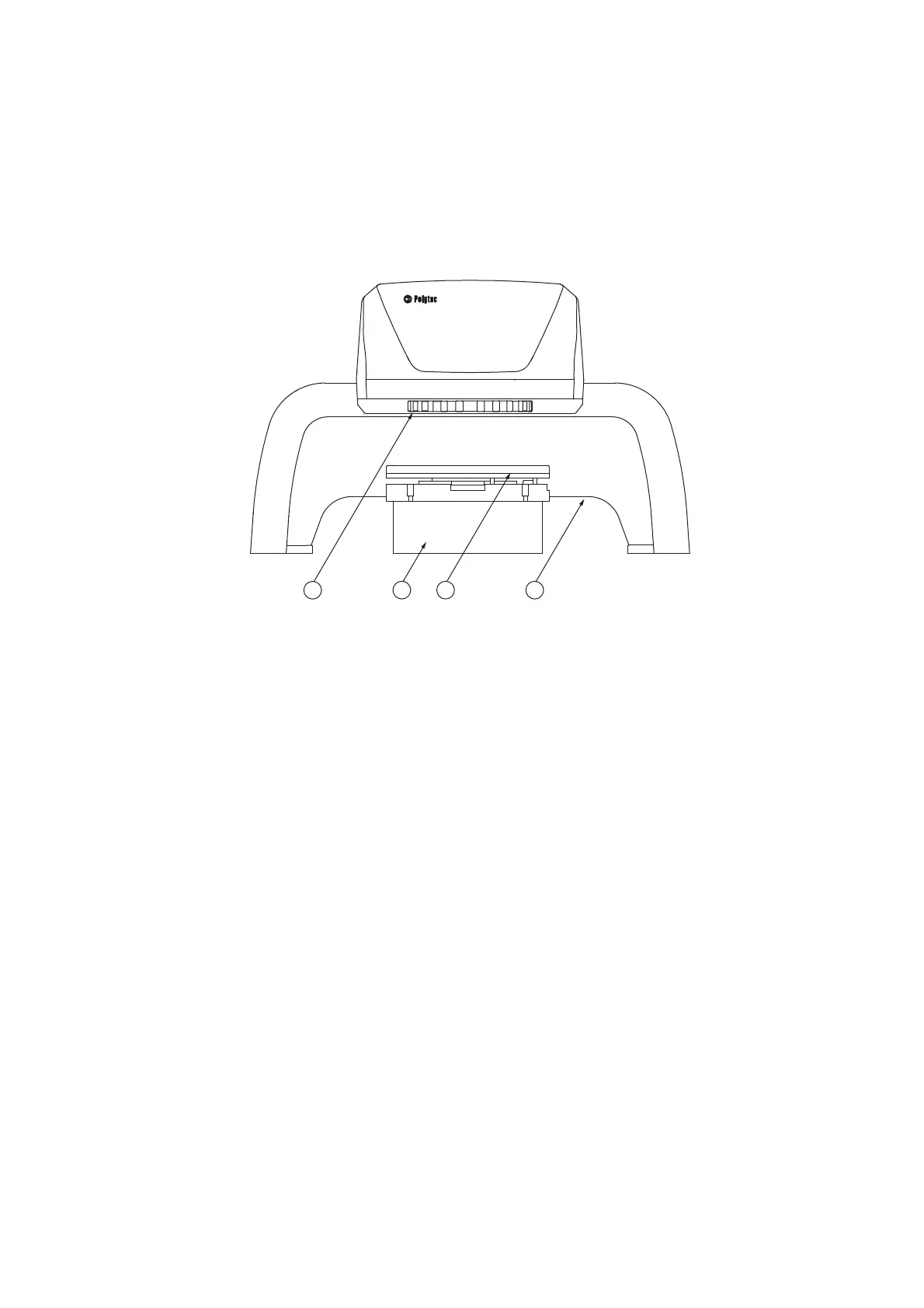
Front view
The front view of the sensor head with stand and tip-tilt unit is shown in the
following figure.
Figure 3.1: Front view of the sensor head with stand and tip-tilt unit
1
Beam exit window with filter wheel
To adjust various object filters
2
Spacer ring
To raise the sample to get the right stand-off distance between the sensor head
and sample
3
Tip-tilt unit
To align the sample relative to the object beam
4
Stand