3-10
3 First Steps
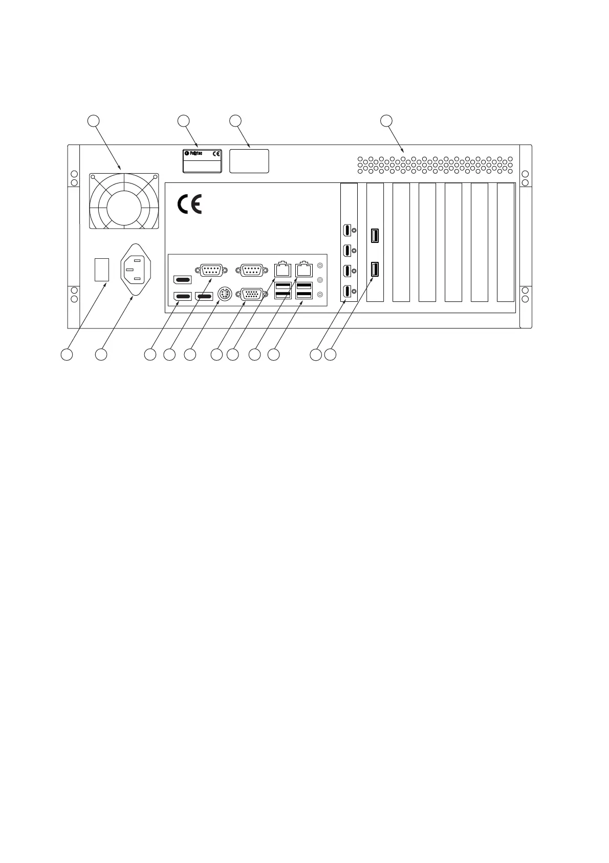
Back view
The back view of the industrial PC is shown in the following figure.
Figure 3.8: Back view of the industrial PC
1
Cooling fan
2
Name plate
Plate with information on model, serial number, power specifications etc.
3
Warning label
4
Air vents
5VIDEO
USB connection
Connection for the USB 3.0 cable to the sensor head to control the video camera
and transmit the video signals.
6 MONITOR
connection (Mini DisplayPort)
Connections for the TFT monitor
7
USB interfaces (Universal Serial Bus, type A)
Alternative connections for peripheral devices such as mouse, keyboard, etc. or
to connect the hardlock to release the software.
8 NETWORK
network connection
Connection option for connecting up to an Ethernet network
9 MOTOR
network connection (motor controller communication)
Connection for the network cable to the controller.
10
Monitor connection (VGA connection)
Not used