3-20
3 First Steps
Test
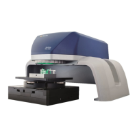
8. Position the Polytec test object within the measurement range [A] on the
object support (refer to the following figure).
The live video image of the Polytec test object is displayed.
Figure 3.13: Measurement range [A] under the beam exit window
9. If the image is too dark or too bright, adjust the exposure time as
described in your TMS software manual.
10. Make a measurement as described in C
HAPTER
4 and in your TMS
software manual.
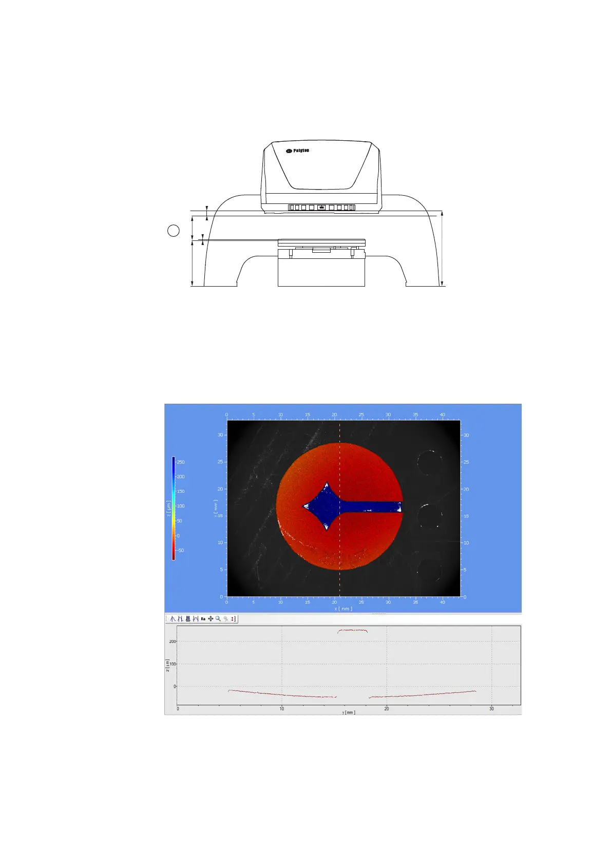
The measurement result should look the same as the following figure.
Figure 3.14: Measurement result of the Polytec test object in the analysis window