6.2. Topology
SD700 drive operates according to the principle of pulse-width modulation (PWM). Varying the power
supply voltage and the grid frequency, it is possible to control the speed and torque of the connected
induction three-phase motors by means of its main components: rectifier bridge, the DC bus, inverter
bridge, and power and control board.
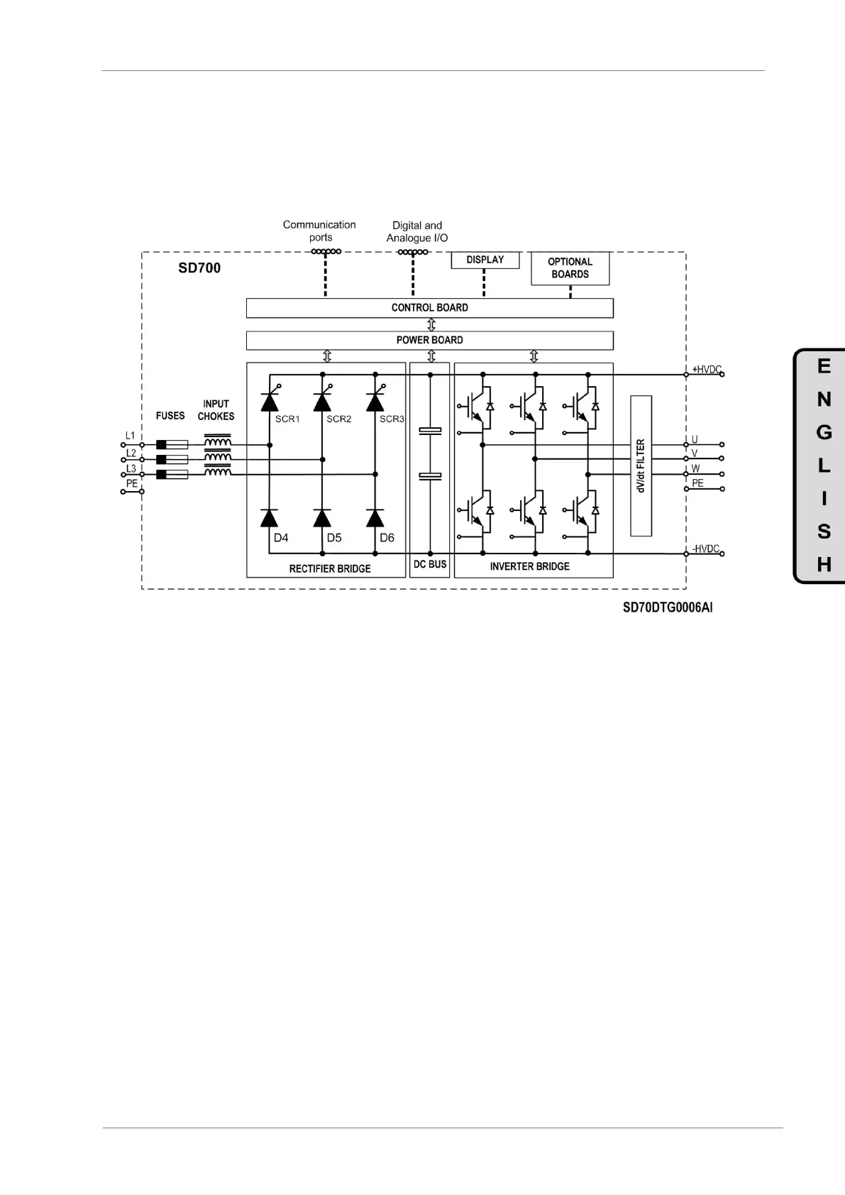
Figure 6.2 General Block Scheme for frames 3 to 11
SD700 integrate as standard input chokes filters. These filters significantly reduce the THDi values, and
increase the impedance line protecting the drive against electrical distortions. Depending on the frame, the
input choke filter is installed in the input side or in the DC bus. For frames 3 to 11 filter is installed in the
input side. For frames 1 and 2 filter is installed in the DC bus (see figure 6.3).
SD700 frames 5 to 11 integrate as standard ultra fast fuses that protect the drive against downstream
overcurrents. Additionally the drive integrates multiple electrical protections that protect the drive and the
motor as a motor relay does.
The SD700 includes a power and a control board to control the rectifier thyristor diode’s bridge shooting,
the inverter IGBT’s bridge shooting, the soft charge, the DC bus voltage and the motor performance. In
addition, control board integrates the interface terminals such as communication ports, the digital and
analogue inputs and outputs, colour touch-screen display and alphanumeric display, etc.
The inverter bridge generates the PWM wave that controls the motor performance (voltage, current, torque,
etc...). SD700 Series by Power Electronics, integrate as standard output dV/dt filters and a CLAMP system
that reduces significantly the dV/dt rise time below 500V/μs - 800V/μs, therefore, it reduces the voltages
peaks at the motor windings, the common mode currents and the EMC emissions.
 Loading...

