Figure 6.10 Recommended cable bundling scheme
CAUTION
Line voltage (input supply) must never be connected to U, V and W terminals.
Otherwise, the drive will be damaged.
It is necessary that installer guarantee the correct observance of the law and the regulations that
are in force in those countries or areas where this device is going to be installed.
Do not use capacitors for power factor correction, surge suppressors, or RFI filters on the output
side of the drive. Doing so may damage these components.
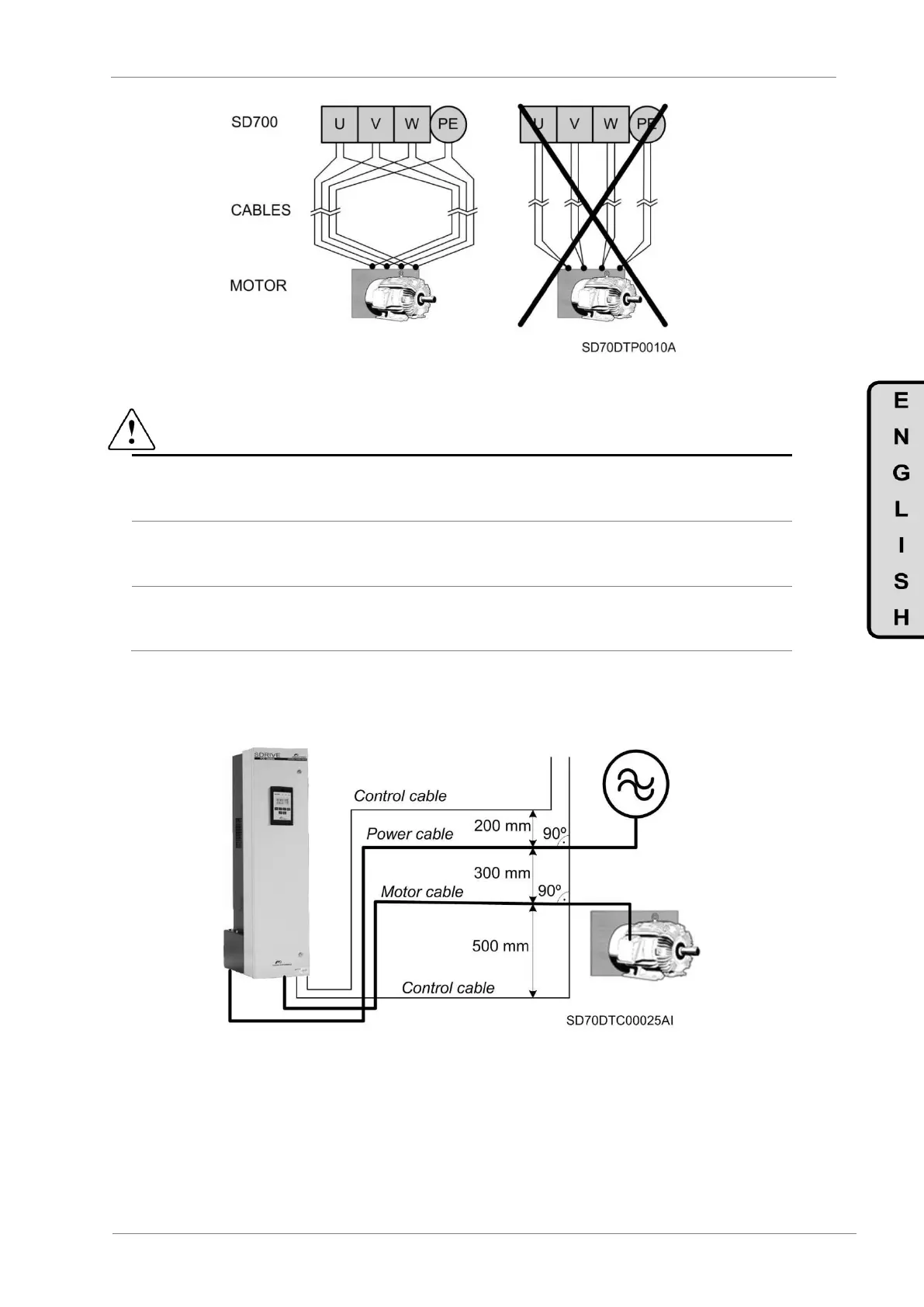
All power conductors, such as input power cables, output motor cables, DC link cables must be routed
separately from the control, signal, PTC, encoder or data cables. The recommended distances between
the cables are shown in the next figure:
Figure 6.11 Cable routing distances
 Loading...

