7.3.1. Safety Integrity Level SIL3- PLe
This assembly provide a highly reliable safety function. When the sensor (E-Push Button) is
activated, the STO function interrupts providing energy to the motor. Therefore, it will stop the motor
by its own inertia or will avoid any possible unexpected start.
The use of an external safety relay permits to monitor all the safety elements and feedbacks signals,
therefore in case a relay failure or elements malfunction the motor will safely stop and a restart will
be prevented. The external safety relay must be SIL3 or PLe certified, and compatible with the
following features: 24Vdc power supply, 2 safety input terminals, at least 2 NO and 1 NC outputs
contacts and a reset function (Ej: PILZ PNOZ X2.P8). The sensors (emergency push buttons,
interlock switches, etc) must be certified as safety elements.
The total probability of a dangerous random hardware failure per hour (PFH) value of all elements,
which are applied for the realization of the safety function, shall not exceed the limit of the
corresponding SIL level. The installation must be performed by trained personal with experience in
functional safety.
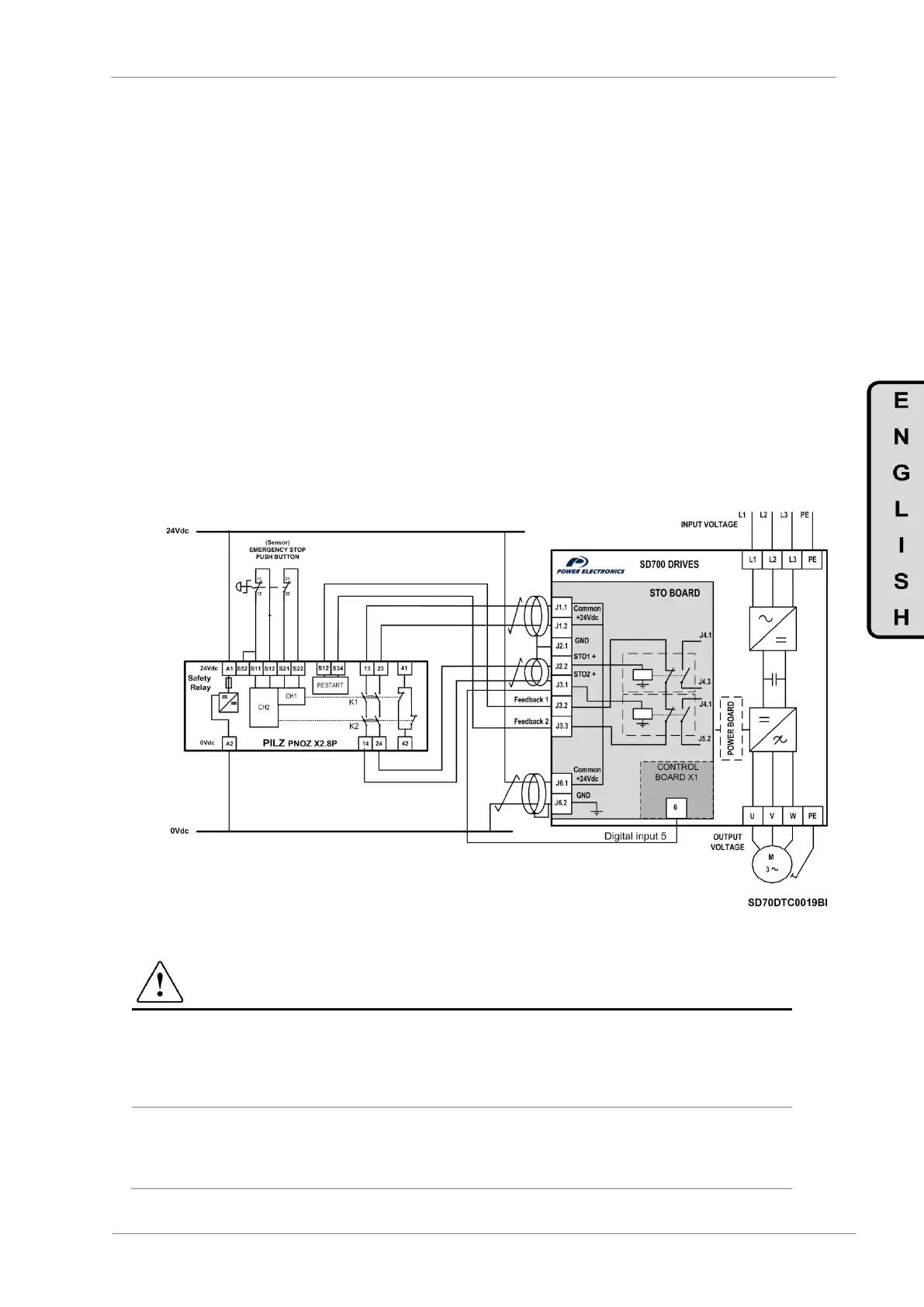
Example 1: Emergency stop (SIL3, PLe) safety function with automatic restart. The STO’s
board power terminals will be connected to an external auxiliary SELV/PELV 24Vdc power supply.
Both input safety channels will be connected to NO contacts of safety relay, and the monitoring
channel (J3.2 and J3.3) will be connected to the terminals of the safety relay restart. To ensure a
correct drive response when a fault occurs, J3.1 terminal must be connected to the digital input 5
of the SD700, previously set as external fault (G4.1.9 option 24 EXTERN EMERGE). It is mandatory
to use a push button equipped with two normally close contacts that will be connected to the relay’s
safety inputs.
Figure 7.7 Example 1- Emergency stop push button
CAUTION
According to EN 60204-1 automatic restart is not allowed after an emergency stop. For this reason
the machine control must prevent an automatic start after emergency stop.
For SIL 3 applications the safety function has to be tested regularly (approximately once per
month) in order to detect certain failures.
To ensure a correct drive response when a fault occurs, J3.1 terminal must be connected to the
digital input 5 of the SD700 drive, previously set as external fault (G4.1.9 option 24 EXTERN
EMERGE).
 Loading...

