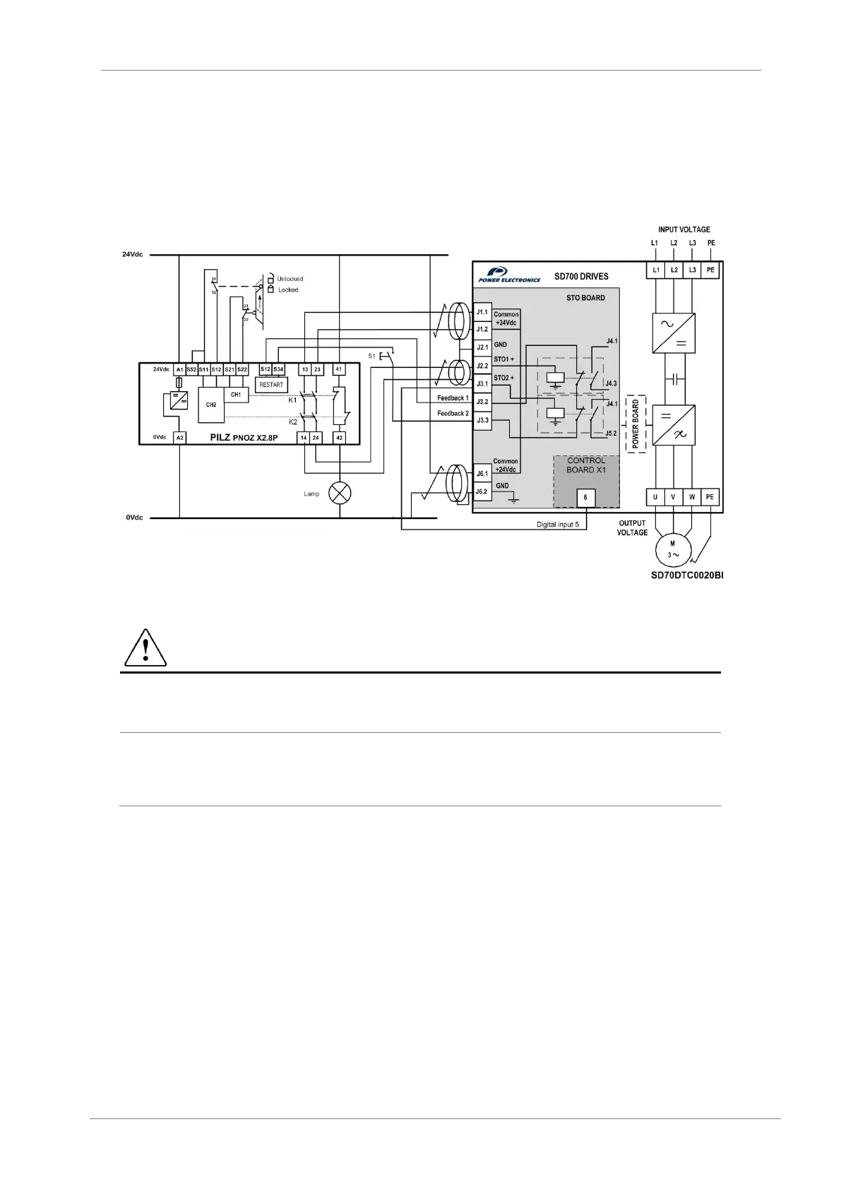
Example 2: SIL3 (PLe) Safety door opening stop for maintenance tasks with manual restart.
This function is used to prevent an unexpected restart when a maintenance task is being carried
out in a risk area. In this case, the relay’s safety inputs will be connected to a safety interlock switch
placed in the door. Additionally a push button is installed to force a manual restart of the safety
relay and a lamp connected to the NC output contact of the external safety relay will indicate the
restart. To ensure a correct drive response when a fault occurs, J3.1 terminal must be connected
to the digital input 5 of the SD700, previously set as external fault (G4.1.9 option 24 EXTERN
EMERGE).
Figure 7.8 Example 2- Safety door opening
CAUTION
For SIL 3 applications the safety function has to be tested regularly (approximately once per
month) in order to detect certain failures.
To ensure a correct drive response when a fault occurs, J3.1 terminal must be connected to the
digital input 5 of the SD700 drive, previously set as external fault (G4.1.9 option 24 EXTERN
EMERGE).
 Loading...

