7.3.2. Safety Integrity Level SIL1- PLc
This connection scheme provides an easy and cost effective solution for installations that not
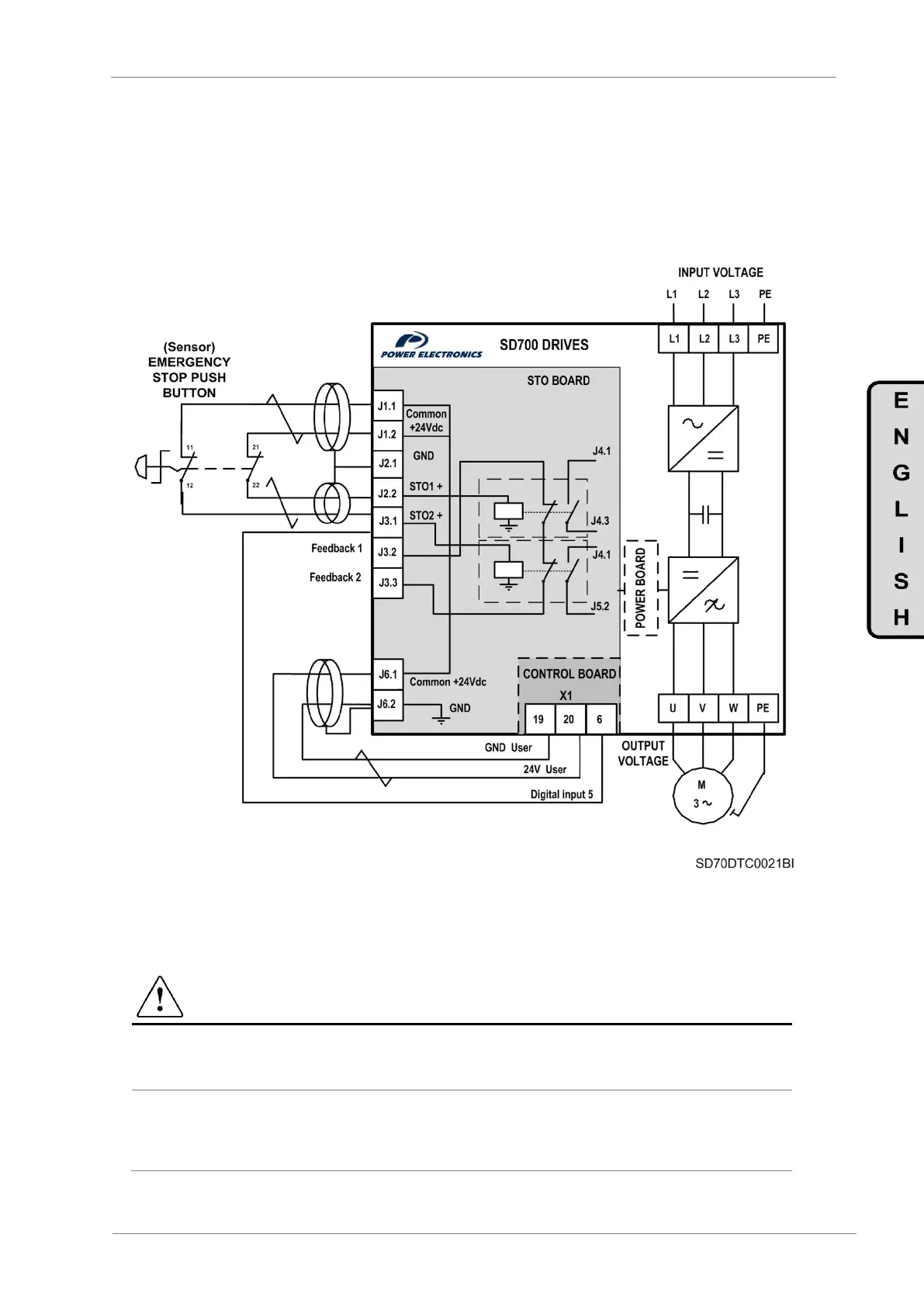
require the highest safety level requirements. In this case, the two NC contacts from the external
push button are directly connected to the optional STO board. As the previous solutions, the
operator pressing sensor will deactivates the IGBT switching of the inverter bridge through two
independent channels, disconnecting the motor power supply and avoiding any possible
unexpected restart. The monitoring terminals will not be connected. To ensure a correct drive
response when a fault occurs, J3.1 terminal must be connected to the digital input 5 of the SD700,
previously set as external fault (G4.1.9 option 24 EXTERN EMERGE).
Figure 7.9 Emergency Stop Push button connection scheme – SIL 1 -PLe
X1.19 and X1.20 terminals can be used for other purpose depending on the inverter applications
(frequency reference performed by an external potentiometer, analogue feedback etc…). In order
to avoid the multiple cable connection in a single terminal (X1.19, X1.20), it is recommended to add
additional external terminals to distribute the power supply.
CAUTION
According to EN 60204-1 automatic restart is not allowed after an emergency stop. For this reason
the machine control must prevent an automatic start after emergency stop.
To ensure a correct drive response when a fault occurs, J3.1 terminal must be connected to the
digital input 5 of the SD700 drive, previously set as external fault (G4.1.9 option 24 EXTERN
EMERGE).
 Loading...

