12.4. Dynamic Braking Unit B150
The Dynamic brake permits to control the regenerated energy for series SD700, SD700KOMPAKT and
SD700FL. B150 dynamic brake activates an IGBT to discharge the DC bus over external resistors when
the DC voltage overpasses a pre-set value. This activation signal could also be delivered by the drive
acquiring an optional Master- Slave mode braking board.
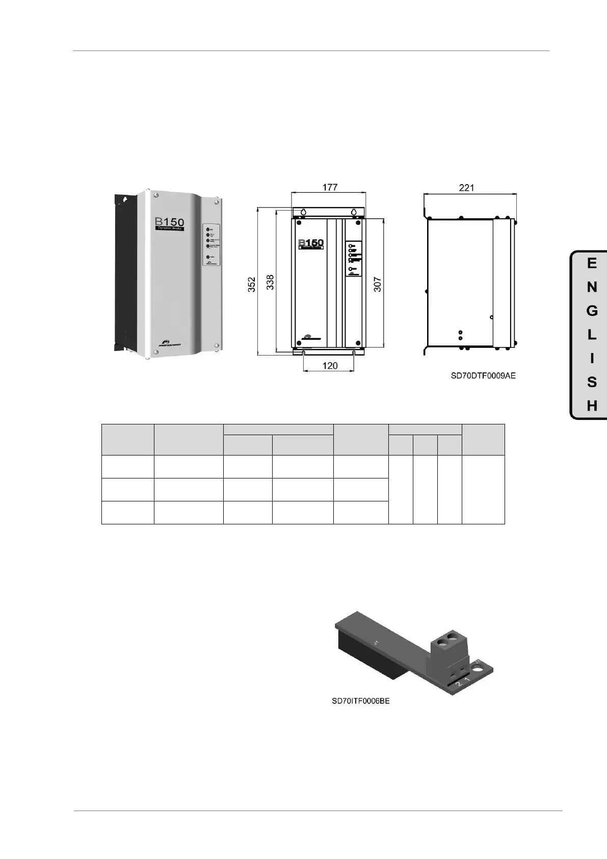
The B150, with reduced dimensions and high reliability, is the main power-switching device of such a
dynamic braking systems.
Figure 12.3 Dynamic Braking Unit. Dimensions [mm]
MINIMUM
RESISTANCE
RATING (Ω)
12.4.1. Optional Board for Slave Mode Brake
There is the possibility for the drive to control the
activation of the dynamic braking module B150.
In this way, the optional board SD7DB must be
used to allowi the drive to control the dynamic
braking unit B150 that will operate as slave unit
of the drive. This optional board is not required
in case of the unit B150 operates in master
mode.
Figure 12.4 Optional Board for Slave Mode Brake
(SD7DB)
 Loading...

