EasyManuals Logo

Power Electronics SD750 Series User Manual

Power Electronics SD750 Series
91 pages
To Next Page IconTo Next Page
To Previous Page IconTo Previous Page
Page #52 background imageLoading...
Page #52 background image
SD750
POWER ELECTRONICS
50
POWER CONNECTION
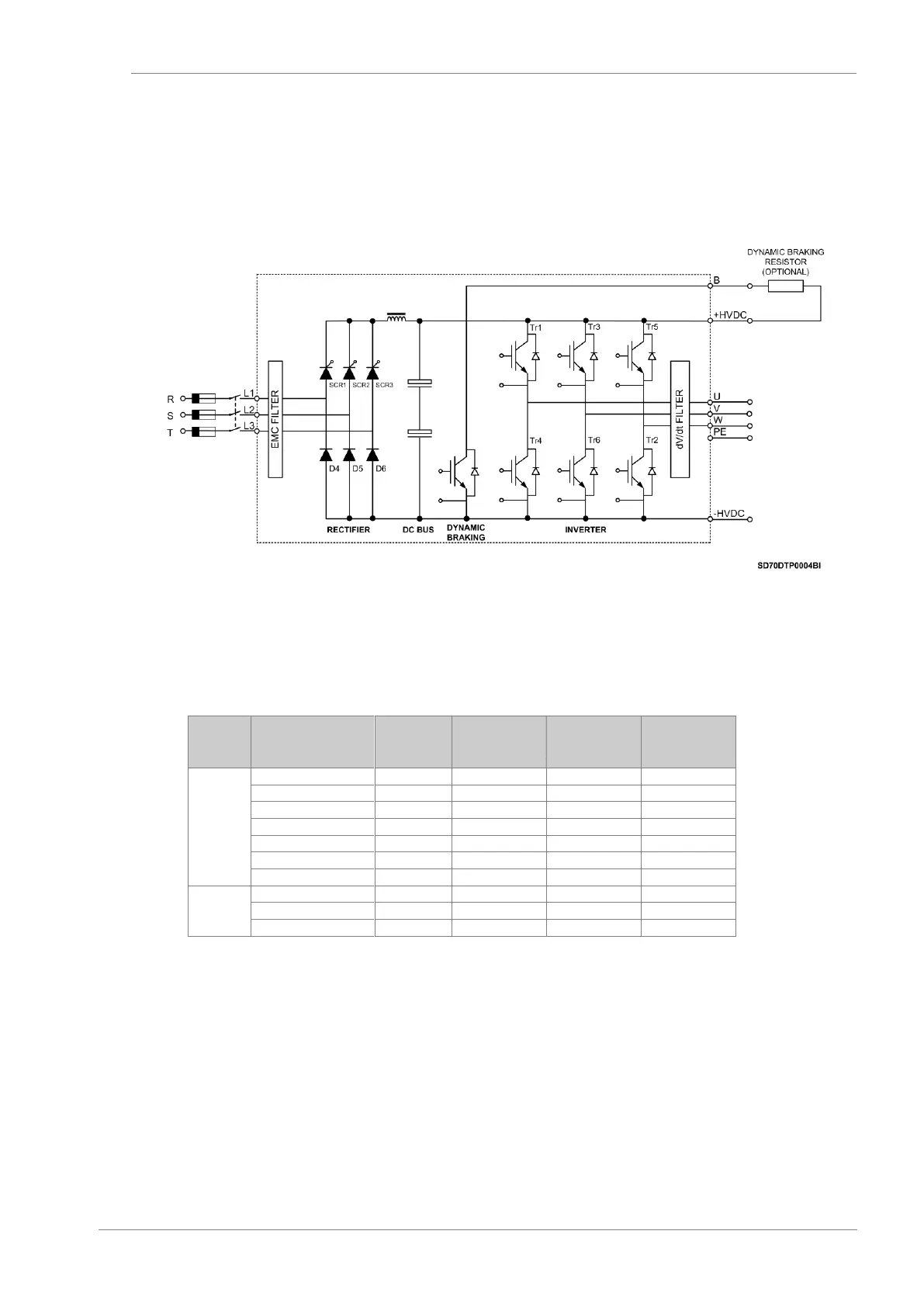
Dynamic Braking Resistors for Equipment of Frames 1 and 2
Frames 1 and 2 equipment include the built-in dynamic brake as standard. The user should only connect
a resistor between terminals +HVDC and B as the following drawing shows.
Power electronics for Frames 1 and 2 equipment
Resistor Values for Dynamic Brake (Optional)
FRAME
CODE
I(A) Rated
Motor Power
(kW) at
400VAC
Dynamic
Braking
Resistor (Ω)
Power of
Braking
Resistor (kW)
1
SD750006 5B06DEF
3
1,5
375
1,5
SD750008 5B06DEF
6
2,2
250
2,2
SD750011 5B06DEF
9
4
140
4
SD750015 5B06DEF
12
5,5
100
5,5
SD750024 5B06DEF
18
7,5
75
7,5
SD750030 5B06DEF
24
11
50
11
SD750040 5B06DEF
32
15
40
15
2
SD750048 5B06DEF
38
18,5
30
18,5
SD750060 5B06DEF
48
22
25
22
SD750075 5B06DEF
60
30
18
30
Note: This table is based on a 100% enable duty (ED). For other ED’s different from 100%, braking
resistors with the same ohmic value shall be used and their power shall be calculated by multiplying
the power of said resistance to 100% (value of the table) by the new ED. Enable Duty means the time
the resistor is working (regeneration). Resistors for 100% of ED = continuous operation. For example,
in case of ED of 30%, it will be multiplied by 0.3.

Table of Contents

Questions and Answers:

Question and Answer IconNeed help?

Do you have a question about the Power Electronics SD750 Series and is the answer not in the manual?

Power Electronics SD750 Series Specifications

General IconGeneral
BrandPower Electronics
ModelSD750 Series
CategoryDC Drives
LanguageEnglish

Related product manuals