The following installation recommendations are suitable for TN and TT grids. For IT grids refer the
dedicated section. Otherwise, you could cause damage to equipment and personnel.
Wiring and periodic inspections should be performed at least 10 minutes after disconnecting the
input power. When removing the front cover, check that the red DC Link LED is off. Afterwards
you can remove the metal cover and check with a multimeter the following measures:
• The voltage between the output plates U, V, W and the cabinet must be around 0V.
• The voltage between the DC link +, - terminals and the chassis must be below 30Vdc.
Otherwise, you may get an electric shock.
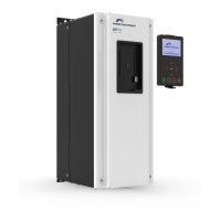
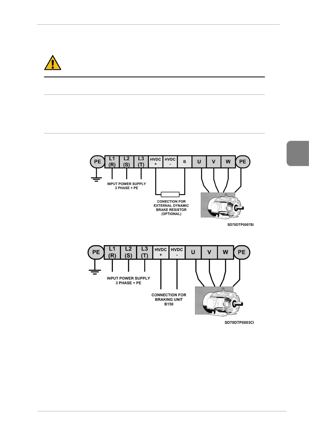
The input and output busbars are labelled according to the following diagram.
Power wiring connection for frames 1 and 2
Power wiring connection for frames 3 to 11
The input terminals L1, L2, L3 and PE (drive power supply), output terminals U, V, W and PE (motor
power supply) must be introduced through the metal plates situated in the bottom part of the cabinet. Do
not drill or mechanize the vents. Otherwise, the drive could reduce its cooling capacity.
The front metal panel corresponds to the motor cables and the rear metal panel to the input cables; these
panels are not delivered neither drilled nor pre-marked to enable any configuration. Each cable must be
equipped with its own cable gland or grommet that prevent dust or moisture from entering the equipment.