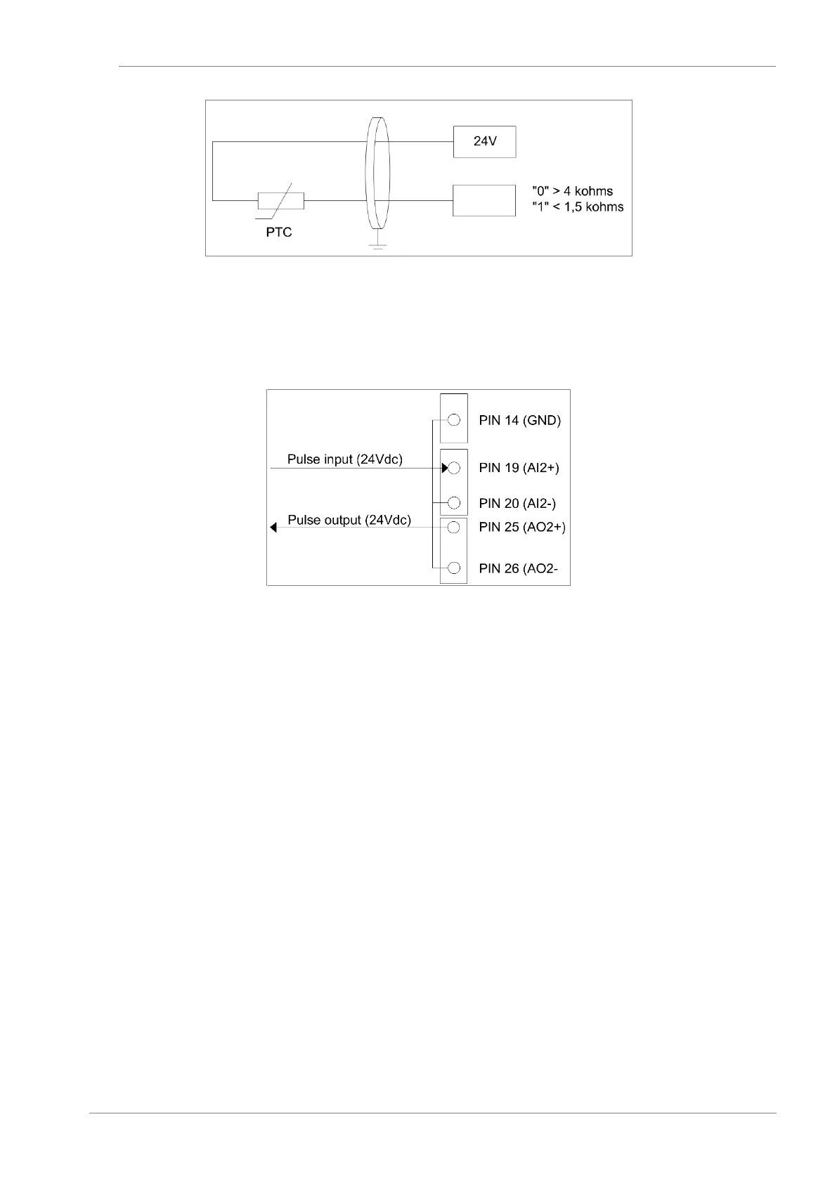
AI2/AO2 (PIN19/25) pulse input/output mode.
Both analogue input and output 2 can be configured as pulse input/output. To do so, bridge J21 must
be connected in the position indicated in the table above and, besides, they must be connected to
GND (PIN 14).
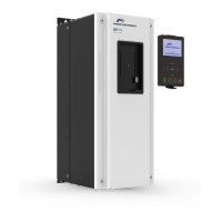
AI3 (PIN 21/22) PT100 mode.
The AI3 allows configuring a PT100 sensor. With this sensor, motor temperature can be measured
continuously. Ground cable screening must be connected only in one end. For further information about
parameter configuration, consult the Software and Programming Manual.
Measurement process:
a. Analogue output is configured in current mode.
b. Analogue input is configured in voltage mode and any of the two analogue outputs in mode 10 mA.
c. A current of 1mA (generated by the analogue output) through the PT100.
d. Voltage in the analogue input is measured.
e. With injected current and voltage, the PT100 resistance is calculated.
f. With the PT100 table, and knowing the resistance, temperature is obtained.
 Loading...