▶
12
Duecanali User Guide
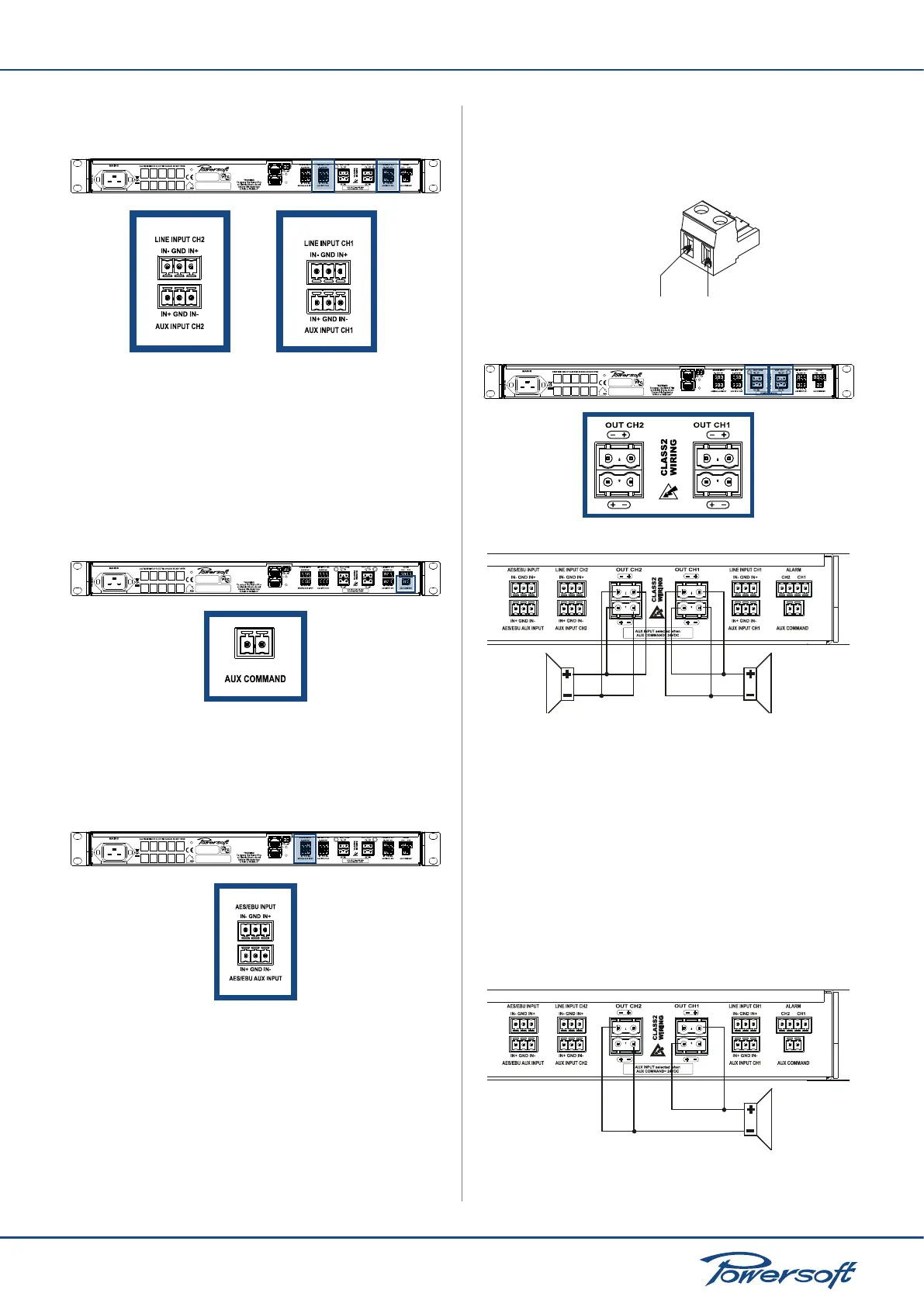
Input connectors are placed on the back of the Duecanali and
grouped in two rows:
FIGURE 9: Rows of input connectors
▶
The topmost line of connectors is for line input
▶
The second row of connectors is for auxiliary input
Line Input/Aux Input toggle:
The amplier switches from line inputs to auxiliary inputs when a
constant 24V DC voltage (± 20%, either polarity) is applied to the
“AUX COMMAND” connector. When this voltage is removed
from the “AUX COMMAND” connector, the unit switches back
from auxiliary inputs to line inputs.
Duecanali Series
FIGURE 10: AUX COMMAND connector
5.1.2 AES/EBU Connection
On DSP equipped ampliers, the AES/EBU connectors are those
illsutrated in the gure below:
Duecanali Series
FIGURE 11: AES/EBU connectors
▶
The topmost line of connectors is for line AES/EBU input
▶
The second row of connectors is for auxiliary AES/EBU input
5.2 Connecting Audio Outputs
Warning! Lethal voltage levels may be present at the loudspeaker
connectors when the amp is turned on!
A a 2-pin Phoenix GMSTB 2.5/2-ST connector is used for the
amplier’s output connections. The + pin of the connector
corresponds to the positive output of the channel. Ensure that the
speakers are connected to the Duecanali output with the correct
polarity.
Phoenix contacts
GMSTB 2.5/2-ST
out (-) out (+)
FIGURE 12: Audio output Phoenix connector
Duecanali Series
FIGURE 13: Output connectors
FIGURE 14: Stereo output connection
5.2.1 Lo-Z and 70V/100V Operations
Any channel of a Duecanali amplier can drive either a lo-Z or a
70V/100V (hi-Z) line. In order to connect any channel’s output to
a 70V/100V line, the output voltage must be limited as described
in “7.4 Max output voltage” on page 19.
5.2.2 Bridge Mode Connection
Bridge mode connection of outputs is possible only in lo-Z
operational mode. The following diagram illustrates how to
connect the Duecanali outputs in bridge mode:
FIGURE 15: Bridge connection of outputs

 Loading...


