▶
23
Duecanali User Guide
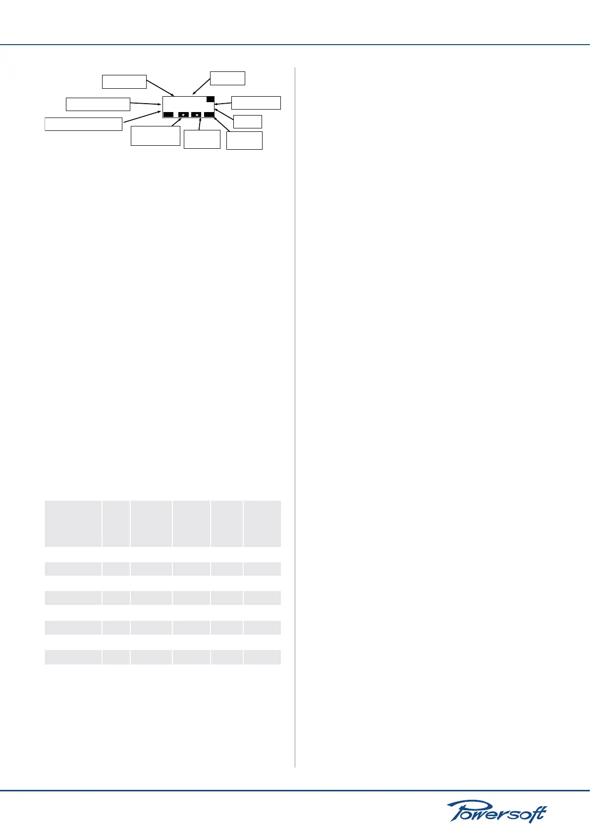
PEQ #12 Peak CH1
Freq=21205Hz G=+12dB
BW=0.63oct Q=21.3
back edit
Filter number
Filter type
Filter frequency (Hz)
Filter Gain (dB)
Filter bandwidth (octaves)
Filter Q
Show next
filter
Show previous
filter
Edit this
filter
FIGURE 37: Parametric Equalizer (PEQ) information window
Specically:
▶
Active: determines if the lter is enabled or not (at response)
Gain(dB): lter gain. Can be set only if the lter is a peaking
or shelving lter. Acceptable values go from -15 to +15dBs in
0.1dB steps
▶
Q factor: quality factor of the lter. This can be user set for
all lters except shelving lters. Acceptable values range from
0.1 to 30 with 0.1 steps.
▶
Bandwidth (oct): the bandwidth of the lter expressed
in octaves around the central frequency. This value is the
inverse of the Q factor; therefore, its value is determined by
setting the Q factor.
▶
Type: allows the user to select the lter type:
1. Peaking
2. Low Shelving (3 to 15dB/oct)
3. High Shelving (3 to 15dB/oct)
4. Low pass EQ
5. High pass EQ
6. Bandstop
7. Bandpass
8. Allpass
By pressing the “edit” button, the settings for the selected lter
can be changed. The following chart summarizes which parameters
can be edited according to the selected lter type.
Parametric Equalizer (PEQ) settings according to lter type:
lter type
Active
on/off
Freq
(20-20kHz,
1/96 steps)
Gain
(-15 to
+15dB,
0.1dB
steps)
Slope
(3-15dB/
oct)
Q factor
(0.1-30,
0.1 steps)
Peaking
✓ ✓ ✓
-
✓
Low Shelving
✓ ✓ ✓ ✓
-
High Shelving
✓ ✓ ✓ ✓
-
Low pass EQ
✓ ✓
- -
✓
High pass EQ
✓ ✓
- -
✓
Bandstop
✓ ✓
- -
✓
Bandpass
✓ ✓ ✓
-
✓
Allpass
✓ ✓
- -
✓
8.2.2.2 LP Filter (and HP Filter)
This menu allows the user to congure the crossover lters.
There are 2 available crossover lters: a lowpass and a highpass.
By combining both, the result will be a bandpass response. Both
traditional IIRs (Innite Impulse Response) as well as brickwall
linear phase FIRs (Finite Impulse Response) are implemented. If a
FIR lter in the EQ section is enabled, a FIR crossover lter cannot
be enabled at the same time. The LP or HP lter can be edited
by the user via the main LCD screen. The parameters that can be
user modied are:
▶
active status
▶
frequency
▶
slope
▶
lter type
The classic IIR crossover lter shapes that can be selected as a high
pass or low pass lter are: Butterworth, Bessel, and Linkwitz-Riley.
In the rst 2 cases, the frequency parameter in the edit window
denes the –3dB point, in the latter, the –6dB point. The slope is
freely selectable from a minimum of 6dB/octave (1st order lter)
to 48dB/octave (8th order lter).
The FIR lters can be selected as normal (FIR Linear Phase) or
enhanced (Hybrid FIR). The enhanced version of the lters gives
a higher rejection of out of band signals, at the expense of a small
(30°@400Hz) phase modication. In both cases, the minimum
working frequency is relative to the desired latency. Standard
setting limit this to 400 Hz. For this reason it is advisable to use
FIR lters to crossover upper midranges or mid-high drivers for
which the phase coherency is a key point.
8.2.2.3 Polarity
This menu allows to reverse the signal polarity. The two selectable
modes are:
▶
In phase: the signal’s polarity is not altered
▶
Reversed: the signal’s polarity is reversed.
8.2.2.4 Channel Delay
This menu allows to set a single channel output delay. This is helpful
to time-align two different loudspeakers on the two amplier
channels. The selectable delay varies from 0 to 32 ms (about 11
meters), with a single sample step (equal to 1/96000th second or
10.4 us, about 3.5 mm)
8.2.2.5 Gain
This menu changes the channel gain, from –40dB to +15dB, with
a 0.1dB step.
8.2.2.6 Limiters
The limiting process in sound reinforcement is a way to protect
loudspeakers from accidental damage; therefore, limiters are a
safeguard against excessive signal peaks and/or signal power. They
not only protect from sudden signal peaks but also they protect
against to an over power delivering.
Bear in mind that limiting does not only prevent occasional
damage, but it rst and foremost guarantees a long component
life. The two main purposes of limiting process are:
▶
Over-excursion: an impulsive signal can reach the speakers
and cause damage due to over-excursion of the voice coil
that is driven out of the magnetic gap (where displacement
exceeds Xmax). This can damage the diaphragm (breaking or
deforming it).
▶
Over-heating: delivering high power to the voice coil may

 Loading...


