▶
19
Duecanali User Guide
or not. The up and down buttons on the “Input select” screen
toggle between the available input sources. The “sel” button locks
the selected option.
The possible input/signal path congurations are:
▶
Analog ==> Out (analog input and direct output)
▶
Analog ==> DSP ==> Out
1
(analog input and internal DSP
processing, output)
▶
AES3 ==> Out
1 and/or 2
(AES3 input, direct output)
▶
AES3 ==> DSP ==> Out
1 and/or 2
(AES3 input, internal DSP
processing, output)
▶
KAESOP ==> Out
2
(AES3 input, direct output)
▶
KAESOP ==>DSP==>Out
1 and 2
(KAESOP input, internal
DSP processing, output)
1
Available only with optional DSP board
2
Available only with optional AESOP board
7.4 Max output voltage
The max output peak voltage of Duecanali Series ampliers can
be set by the user. It is possible to set output peak voltage levels
for channel 1, channel 2 or both by pressing the “C1+2” button.
The “+” and “-” buttons change the value of the max output
peak voltage.
FIGURE 28:
Max output voltage
back - +
C1+2
102 102Vpeak
Max output voltage settings screen
The ranges available are shown in the table below:
Amplier model Peak output voltage (V)
Duecanali 3904 40 to 140
Duecanali 5204 40 to 165
Limiting the maximum output voltage is necessary when a
Duecanali amplier is used to drive a 70 V or 100 V distributed
line. The following chart summarizes the max output voltage
levels to set according to the type of distributed line to drive:
Distributed line voltage Peak output voltage (V)
70 V 100 V
100 V 140 V
These voltage values are valid for all Duecanali series ampliers.
7.5 Max mains current
The maximum current the amplier can draw from the mains can
be set by the user through the front panel of all Duecanali Series
ampliers.
Max mains current
back
fast
- +
23 A rms
FIGURE 29: Max mains current set up screen
The “+” and “-” buttons allow setting of the value of the max
rms mains current. Acceptable values are within the 8 A to 16 A
for all Duecanali ampliers. Setting the maximum mains current
determines the current threshold at which a C-Type current
breaker will trip.
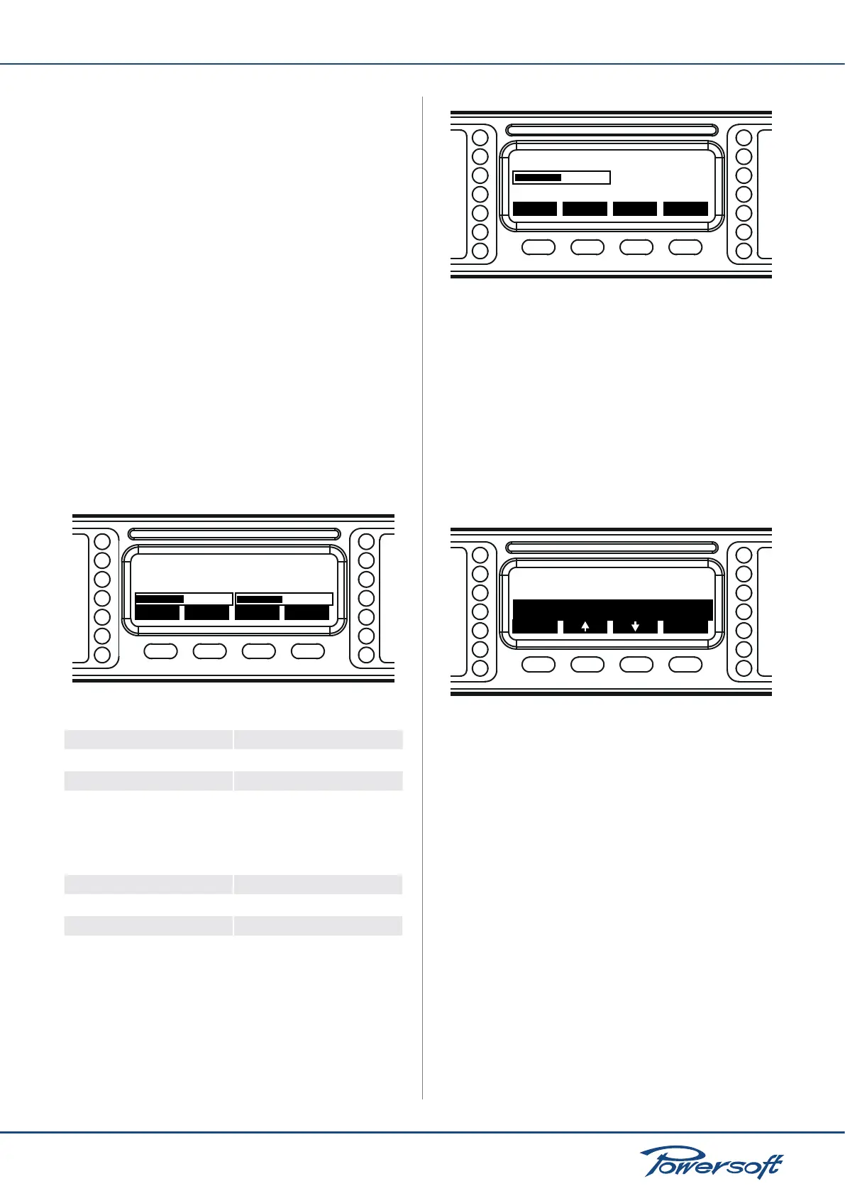
7.6 Clip Limiter CH1 - CH2
The clip function can be used to prevent distortion caused by
clipping of the excessive output signal amplitude. This feature can
be disabled or enabled by pressing the on/off button in the when
the clip limiter voice is selected in the Amplier settings menu:
Max mains current
back
sel
Clip Limiter CH1:ON
Clip Limiter CH1:ON
FIGURE 30: Clip limiter setting for channels 1 and 2 separately
Please note that clip limiters can be set independently for both
channels.
CAUTION: disabling clip limiters can potentially damage
loudspeakers. The amplier’s internal clip limiters should not
be deactivated unless the limiting function is implemented by an
external device such as digital system controllers. In this case,
it is extremely important to correctly set limiting parameters in
order to preserve loudspeakers from excessively powerful and
potentially hazardous driving signals.
7.7 Gate CH1 - CH2
This function allows to mute the amplier channels individually
if the input signal amplitude falls below the values shown in the
following table:

 Loading...


