▶
47
Duecanali User Guide
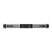
19.2 Duecanali 3904 DSP+AESOP
Specications
General
Number of channels 2
Output power stereo mode mono-bridged mode
EIAJ Test Standard, 1 kHz, 1% THD 2 Ω/ch 4 Ω/ch 8 Ω/ch 70 V/ch
1)
100 V /ch
1)
4 Ω 8 Ω
2,400 W 1,950 W 1,400 W 1,800 W 2,400 W 4,800 W 3,900 W
Max output voltage / current 140 V
peak
/ 102 A
peak
AC Mains Power
Power supply Universal, regulated switch mode with PFC (Power Factor Correction)
Operating voltage 100 - 240 V ±10%, 50/60 Hz
Power factor cos (
φ) >0.95 @ >500 W
Consumption / current draw @ 230 V @ 115 V
Idle 75 W 1.3 A 64 W 1.12 A
I/8 of max output power @ 4 Ω 609 W 3.1 A 609 W 6.3 A
I/4 of max output power @ 4 Ω 1,219 W 5.7 A 1,219 W 11.4 A
Thermal
Environmental operating temperature 0° - 45° C / 32° - 113° F
Thermal dissipation Fan, continuously variable speed, temperature controlled, front to rear airow
Idle 382 BTU/h 96 kcal/h
I/8 of max output power @ 4 Ω 722 BTU/h 182 kcal/h
I/4 of max output power @ 4 Ω 1,062 BTU/h 268 kcal/h
Audio
Gain, selectable 26 dB 29 dB 32 dB 35 dB
Input Sensitivity @ 8 Ω 4.48 V 3.17 V 2.25 V 1.59 V
Max input level 27 dBu 24 dBu 21 dBu 18 dBu
Gate -54 dBu -57 dBu -60 dBu -63 dBu
Frequency response 20 Hz - 20 kHz (1 W @ 8 Ω, ±0.5 dB)
S/N ratio (amplier section) >110 dBA (20 Hz - 20 kHz, A weighted)
Crosstalk separation > 70 dB @ 1 kHz
Input Impedance 10 k Ω balanced
THD+N/SMPTE IMD/DIM 100 IMD <0.2% from 1 W to full power (typically <0.05%)
Slew rate 50 V/µs @ 8 Ω, input lter bypassed
Damping factor @ 8 Ω >5000 @ 20-200 Hz
DSP
A/D converter
Dual 24bit 96 kHz Tandem® architecture with 127 dBA of dynamic range and THD <0.005% (20 Hz - 20 kHz)
D/A converter
Dual 24bit 96 kHz Tandem® architecture with 122 dBA of dynamic range and THD <0.003% (20 Hz - 20 kHz)
Memory & presets 8 MB (RAM) plus 2 MB (ash for presets); 50 presets stored locally + 150 stored on a smartcard
Digital audio input AES3 (glitchless fallback to analog audio selectable)
Delay for time alignment up to 4 s on the input section, up to 32 ms per output, sample-by-sample stepping
Crossover lters Butterworth, Linkwitz-Riley, Bessel, arbitrary asymmetric, 6 dB/oct to 48 dB/oct (IIR), linear phase (FIR), hybrid (FIR+IIR)
Output equalizer 16 fully parametric lters per channel, IIR: peaking, hi/lo shelving, hi/lo pass eq, band pass, band stop, all pass. Custom FIR up
to 384 taps @ 48 or 96 kHz
Input equalizer Three layers (PEQ, raised cosine, shelving), 32 lters each + group lters, up to 256 lters per channel
Cable compensation network up to 2 Ω negative/positive wire compensation (Active DampingControl
TM
)
Limiters
Power limiter (TruePower™, RMS voltage, RMS current) + Peak Limiter
Front Panel
Indicators 7 meter LEDs: 5 x green, 1 x yellow, 1 x red, top yellow and red show alarm with protect description on LCD panel
Controls
4 pushbuttons, function depending on user menu; mains switch
Maintenance
SmartCard reader/writer for rmware updates and preset storage. Dust lter foam behind front panel
Rear Panel
Audio signal input connectors
Analog: main & aux each 2 x 3-pin Phoenix MC1.5/3-ST-3.81, electronically balanced (aux activated per aux voltage)
Loudspeaker output connectors
4 x 2-pin Phoenix type GMSTB2.5/2-ST
Fault alarm connector 1 x 4-pin Phoenix type MC1.5/2-ST-3.81
Aux command input 1 x 2-pin Phoenix MC1.5/2-ST-3.81
Aux external voltage 1 x 2-pin Phoenix MC1.5/2-ST-3.81
Network data port Ethernet 2 x RJ45 with activity LEDs
Network dataport AESOP incl. AES3
AES3: main & aux each 2 x 3-pin Phoenix MC1.5/3-ST-3.81, electronically balanced (aux activated per aux voltage)
AC mains
IEC C19/22.2 20 A, AC mains cord with 20 A 3-pin plug 20 A for US, IEC Schuko 16 A for every other nation
Controls
1 x link switch, linking analog inputs 1 and 2
Construction
Dimensions W 483 mm / 19”, H 44.5 mm / 1 RU, D 360 mm / 14.2”
Chassis 1 mm / 0.04” steel chassis; 3 mm / 0.12” screw hole protection, side reinforcement & rear support, 0.8 mm (0.03”) steel
removable dust cover
Weight
8 kg (17.7 lb)
1) with voltage limiter activated (70V/100V) and with an external HP filter (100V)
Pilot Tone Detection, Generation and Output Load Monitor (optional)
Input pilot tone detection 0 V
RMS
- 1 V
RMS
in steps of 10 mV
RMS
; 20 Hz - 22 kHz in steps of 10 Hz
Output pilot tone detection 0 V
RMS
- 30 V
RMS
in steps of 0.1 V
RMS
; 20 Hz - 22 kHz in steps of 10 Hz
Impedance alarm 20 Ω - 1000 Ω in steps of 0.1 Ω; 20 Hz - 22 kHz in steps of 10 Hz; Impedance vs frequency measurement
Output generator 1 V
RMS
- 10 V
RMS
in steps of 1 V
RMS
; 20 Hz - 22 kHz in steps of 10 Hz, one independent generator for each channel
 Loading...
