▶
13
Duecanali User Guide
5.2.3 Internal Signal Path Polarity
In order to increase the power’s supply energy storage efciency,
signals coming from channels 1 and 2 are polarity reversed one
with respect to the other when entering the amplier. This
ensures a symmetrical use of the voltage rails: if, for example,
both channels’ 1 and 2 input signals are going through a peak at
the same time, channel 1’s energy will come from the positive
voltage rails while channel 2, whose polarity is reversed with
respect to channel 1, will be fed energy from the negative voltage
rails. In this manner, the power supply will work symmetrically,
with one channel catered by the positive rails and the other by
the symmetrical negative rails. Channel 2’s signal will be polarity
reversed once more to ensure that both channels output with
the same polarity as their corresponding input signals. For this
reason it is very important not to invert the polarity of either
channels before feeding them to a Duecanali Series amplier. A
double polarity inversion (the rst by the user inserting the input
signal and the other by the amplier’s internal circuitry) results
in no inversion at all. If this were the case, both channels would
be weighing on only one side (positive or negative) of the power
supply’s voltage rails. This would result in an inefcient use of the
power supply’s energy.
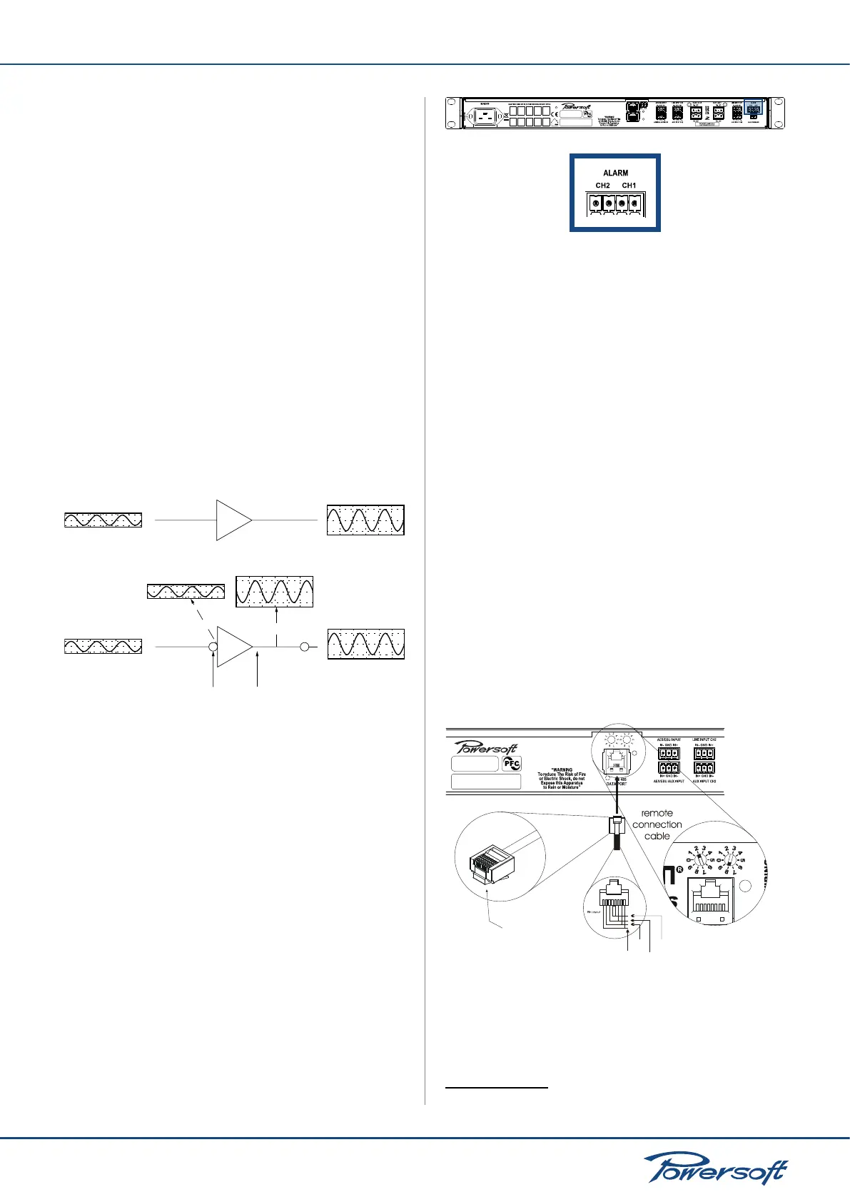
FIGURE 16:
first polarity
inversion
second polarity
inversion
Channel 1
input
Channel 2
input
output
Channel 2
output
Internal signal path polarity with example input signals.
Both channels 1 and 2 are fed the same sine signal
Please pay special attention in using balanced inputs on all
measurement equipment (such as oscilloscope probes) when
you are bench testing.
5.3 GPIO Operations
General Purpose Input/Output Operations (GPIO) can control
or can be controlled by another system. The Duecanali’s GPIO
system implements digital trigger signals to broadcast alarms or
allow remote unit on/off switching.
5.3.1 Alarms
To ensure problem-free and efcient interaction with external
devices, the Duecanali provides one 4-pin Phoenix MC 1.5/12-ST-
3.81 connectors on the back panel for channels 1 and 2.
Duecanali Series
FIGURE 17: Back panel alarm output connectors
These contacts are used to report potentially dangerous faults or
generally unsafe operation conditions by toggling alarm switches
relative to events such as:
▶
DC presence at the output: when a dangerous DC component
is present in the output power signal
▶
Thermal stress: when heat dissipation is not sufcient and
heat sink temperature rises.
In normal operating conditions, the pin for each channel are short
circuited (NC: Normally Closed). When an event capable of
generating an alarm occurs, the 2 pins become an open circuit.
Please refer to section “8.3.2 Diagnostics” on page 27 for a list
of additional alarm triggering events.
5.4 Remote Control Connection
5.4.1 Serial Connection
1
Duecanali Series ampliers with an optional KAESOP board
can be remotely controlled via an RS485 connection. Remote
connection data cables must have an 8 pin modular plug to be
inserted in the RJ45 jack labelled “DATAPORT” on the rear of
the amplier. By plugging an 8 pin modular plug and selecting the
unit’s remote ID via the rotary trimmers, the amp is ready to be
remotely controlled. Please see FIGURE 18 for details.
FIGURE 18:
8 pin
modular
plug
ID selection example
ID = 28
Vext
GND
485+
485-
Remote connection jack, plug and ID selection
1
For Duecanali 3904 or Duecanali 5204 only

 Loading...