▶
14
Duecanali User Guide
Remote connection jack pinout chart:
1 GND
2 Vext
3 485 -
4 485 +
5 485 +
6 485 -
7 Vext
8 GND
5.4.2 Ethernet Connection
2
Duecanali Series ampliers can be remotely controlled via an
Ethernet connection if provided with a KAESOP board. Two- or
four-ports ampliers allow Ethernet data connections with a
variety of possible topographies. See “9 Network Operations”
on page 28 for more details. If four plugs are present (2 in the
front and two in the back of the amp), the pair in the back are
master ports, while the two in front are the slave ports.
FIGURE 19:
Pin Layout
8 pin
modular
plug
100BaseT RX/TX +
100BaseT RX/TX -
100BaseT TX/RX +
AES3-A RX/TX +
AES3-A RX/TX -
100BaseT TX/RX -
AES3-B RX/TX +
AES3-B RX/TX -
Ethernet connection ports for 2-port and 4-port
ampliers
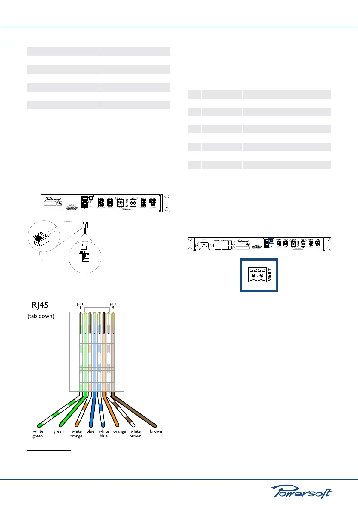
FIGURE 20:
RJ45 jack pinout for KAESOP connections
2
For Duecanali 3904 DSP+AESOP or Duecanali 5204
DSP+AESOP only
The RJ45 TIA/EIA 668-A LEDs are coded s follows:
green LED: indicates the passage of control data
yellow LED: indicates the passage of AES3 signals
Remote connection jack pinout chart:
pin color RJ45 KAESOP pin out
1 white/green 100BaseT AutoMDI RX/TX +
2 green 100BaseT AutoMDI RX/TX -
3 white/orange 100BaseT AutoMDI TX/RX +
4
blue
AES3-A RX/TX +
5
white/blue
AES3-A RX/TX -
6
orange
100BaseT AutoMDI TX/RX -
7
white/brown
AES3-B RX/TX +
8
brown
AES3-B RX/TX -
5.4.3 V ext
The “V ext” terminal, located on the rear panel of the Duecanali, is
used to supply the amplier’s internal Ethernet controller with the
minimum required power for remote on/off switching operations.
When the V ext port is powered by and external 9 V- 12 V DC
(1 A) power supply, the Ethernet controller is enabled to listen for
incoming connections such as device power-on commands.
Duecanali Series
FIGURE 21: Vext connector
5.5 Amplier Setup and Settings
5.5.1 Introduction
In all Duecanali Series ampliers, the combination of the front
panel buttons together with the LCD display allow the user access
to detailed information and complete control over the amplier’s
status. Each button has multiple functions and the display shows
the current active function for each button. This chapter illustrates
all the functions and settings accessible via the amplier front panel.
FIGURE 4 illustrates all Duecanali Series front panel elements.
Armonía Pro Audio Suite
All the setup and settings functions described in this section can be
accessed through a computer by installing Powersoft’s Armonía
Pro Audio Suite software. Armonía is a software environment
entirely developed in-house by Powersoft. Its two main features
are full end user remote control of the amp and its signal processing
capabilities. The intuitive interface provides reliable information
and real time control of all DSP functions (see “18.4.1 Powersoft’s
Armonía Pro Audio Suite” on page 42). Refer to the Armonía
 Loading...


