▶
24
Duecanali User Guide
lead to overheating of the voice coil copper and the relative
magnetic gap. This can damage the isolation copper or burn
out the copper. Another evident high power driving effect is
power compression, noticeable in low frequency speakers.
In order to prevent the two mentioned phenomena two kinds of
limiters are provided:
▶
Peak limiter: protects against mechanical damages. The
peak limiter may also be used to control amplier clipping.
Designers should set this limiter’s parameters as a function of
both the maximum displacement (Xmax) of the diaphragm as
well as the speaker’s maximum tolerated voltage.
▶
RMS limiter: protects speakers against thermal damage when
excessive power is applied for extended periods of time,
resulting in overheating and, eventually, burning. Designers
should be aware of the maximum long term power safely
applicable to speakers (AES power rating). An interesting
approach to RMS limiting is one that uses coil temperature
control. A complete knowledge of the driver’s limits allows to
keep the temperature level in a safe interval not only to avoid
damage but to maintain the speaker in a “linear” zone that
avoids power compression.
Peak Limiter
The peak limiter avoids potentially dangerous displacements of
the cone (an excursion larger that allowed). It acts by reducing
the amplier gain in order to reduce the measured output peak
voltage. Use the declared Peak power or twice the Program power
as a loudspeaker safe-zone output power. The peak limiter’s setting
do not change with the number of parallel speakers connected to
the amplier; this is because the same voltage is applied to all the
components in a parallel circuit. When deciding parameters for a
peak limiter of an amplier with many loudspeakers connected to
it in parallel, the peak power to be taken into consideration is that
reaching only a single speaker.
V
peak
2
P
peak
=
V
peak
=
R
Where R is the nominal impedance of only ONE driver, P
peak
is the peak power and V
peak
is the peak output voltage. A peak
limiter, used with a very rapid onset (i.e., with a very short attack
time), can also be useful in limiting the maximum peak voltage in
distributed constant voltage lines.
Powersoft designed the Duecanali Series limiters as protective
measures; therefore, they are not meant to “color” the sounds
such as dynamic compressors can do. With this in mind, time
constants for these limiters should be selected so as to limit
potentially harmful phenomena which persist for no more than
one or two periods of the related signal bandwidth. To limit
the dangers of dangerous very fast transient signals, all limiters
implement a look ahead time of 0.5s.
The following table gives a few examples of attack and release
times with respect to the frequency range of the signal to be
limited:
FREQUENCY
RANGE (Hz)
AT TACK
TIME (ms)
AT TACK /
RELEASE
R ATIO
RELEASE
TIME (ms)
<63 45 x16 720
63-125 16 x16 256
125-250 8 x8 128
250-500 4 x8 32
500 -1k 2 x4 8
>1k 1 x2 2
The peak limiter menu allows the user to dene the following
parameters:
▶
Active: toggles the power limiter’s on/off status
▶
Threshold (V
pk
): the peak voltage threshold at which the gain
begins to be reduced
▶
Attack: the attack time, i.e. the response time of the limiter
intervention
▶
Release: the decay time, i.e. the time constant after which
the limiter’s action is released and the gain restored to the
nominal value.
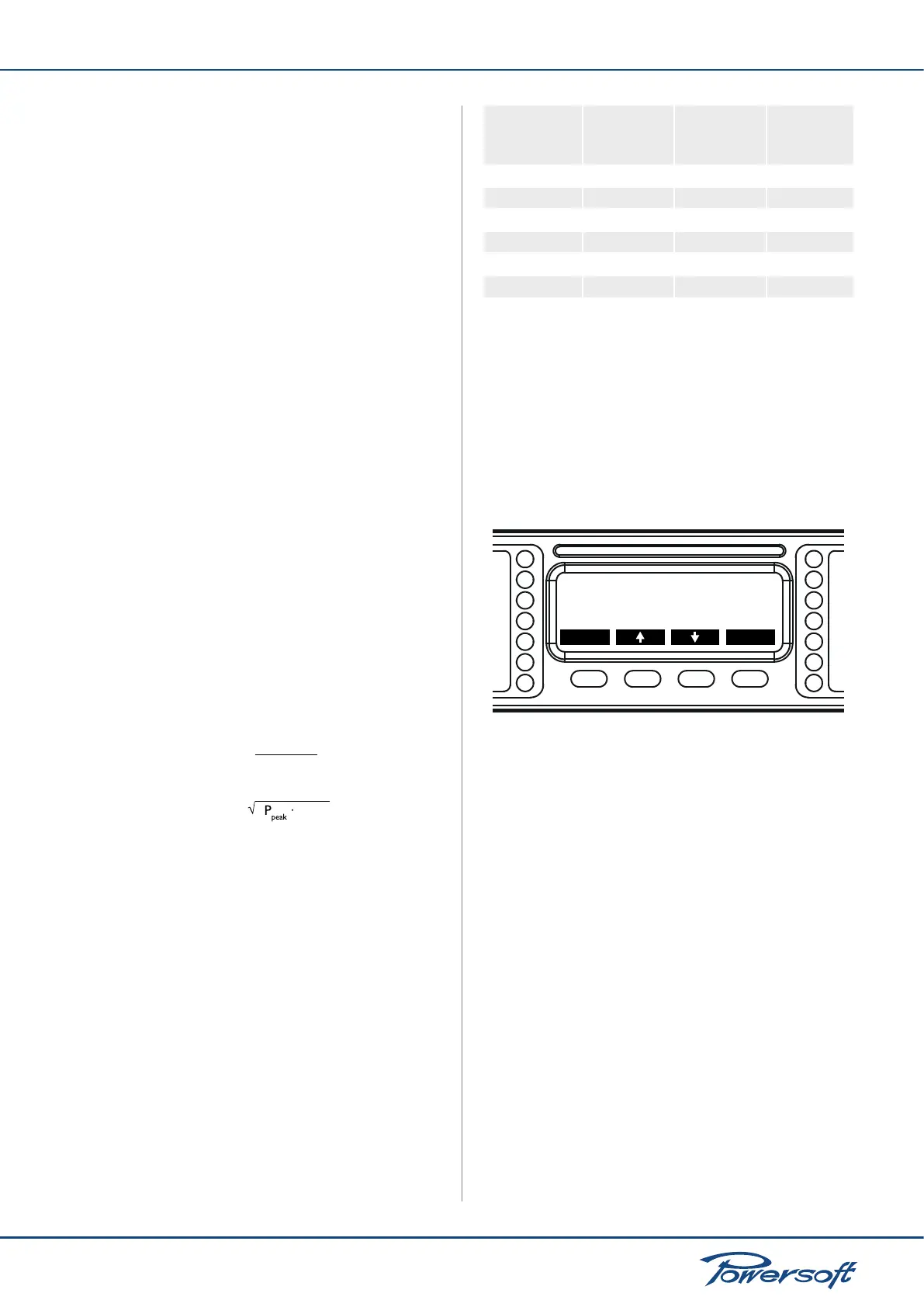
Active:ON
back sel
Thresh.(Vpk):169
Attack(ms):10
CH1
FIGURE 38: Peak limiter main screen
In order to avoid choking the exceptional dynamic range offered
by Duecanali Series ampliers, the peak limiter is designed to
ignore signal peaks lasting less than the attack time parameter.
Moreover, the limiter has an additional lookahead buffer to soften
clipping and minimize distortion, effectively yielding superior sonic
performance. The lookahead time is 0.5 ms.
When tweaking the peak limiter’s levels, it is preferable to rst
setup the time parameters, and then adjust the threshold voltage.
When editing the threshold value, the display shows the gain
reduction (GR) in dBs enforced by the limiter. This information,
together with the limiting voltage referred to the signal in the input
amplier stage (I) expressed in dBus, is displayed in real time to
allow monitoring of the limiting actions as they are performed.

 Loading...