Audio connections
12
12 : 1.Input connections
Powersoft X8 and X4 implement up to four audio in-
put connetions per channel: one analog and three digital
streams.
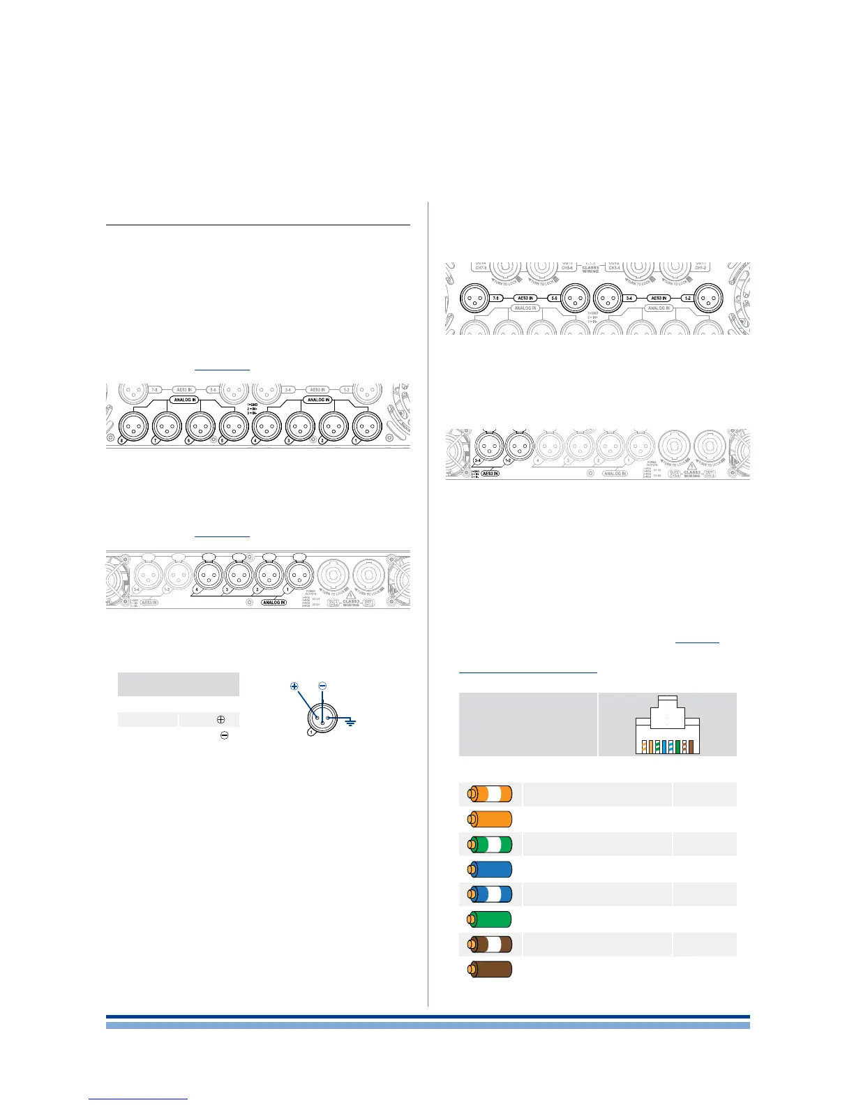
12 : 1.1. Analog input
X8. Analog input is provided by means of eight Neutrik
XLR female connectors, one per channel input. Signal po-
larity is shown in FIGURE 17.
X4. Analog input is provided by means of four Neutrik
XLR female connectors, one per channel input. Signal po-
larity is shown in FIGURE 17.
12 : 1.2. Digital input
Digital input is supported via AES3 (aka AES/EBU) and
Dante™ standard protocols.
The AES3 connection carries a channel pair through a
110 Ω nominal impedance wire in the form of a balanced
(differential) digital signal: in AES3 XLR connectors the iden-
tication of hot and cold pins is not an issue; take care to
never tie pin 2 or pin 3 (balanced signals) to pin 1 (ground).
Avoid the use of microphone cables in AES connections:
impedance mismatch can result in signal reections and
jitter, causing bit errors at the receiver.
X8. The X8 amplier platform implements four physical
AES3 Neutrik XLR female connectors (one per channel pair),
allowing eight discrete AES3 input streams.
X4. The X4 amplier platform implements two physical
AES3 Neutrik XLR female connectors (one per channel pair),
allowing four discrete AES3 input streams.
Two Neutrik etherCON ports are located on the right-
most side of the X8 and X4 rear panels. Fast Ethernet (IEEE
802.3u, 100 Mbit/s) and Gigabit Ethernet (IEEE 802.3ab,
1 Gbit/s) network protocols are supported; Cat5e or Cat6
standard twisted pair cables shall be used for connections
up to 100 meters (328 ft).
EtherCON or RJ45 must comply to TIA/EIA-568-B and
adopt the T568B scheme pinout, as show in TABLE 3.
For more details about the network conguration, refer
to Section: Networking (p. 15).
RJ45 connector
seen from
the front end
12345678
Color code (TIA/EIA-568-B) Pin
ORANGE / WHITE 1
ORANGE 2
GREEN / WHITE 3
BLUE 4
BLUE / WHITE 5
GREEN 6
BROWN / WHITE 7
BROWN 8
TABLE 3: EtherCON/RJ45 T568B scheme pinout.
Analog input
XLR-F pinout
Pin 1 GND
Pin 2
HOT
Pin 3
COLD
HOT
12
3
COLD
GND
FIGURE 17: Analog input connector pinout.
FIGURE 16: X4 - analog input XLR connectors.
FIGURE 15: X8 - analog input XLR connectors.
FIGURE 18: X8 - AES3 input XLR connectors.
FIGURE 19: X4 - AES3 input XLR connectors.
12 | X Series | User guide