User interfaces | 21
Three different backup policies can be selected:
f manual – switching of the input source is demanded
to the user;
f digital validity – in case of no signal presence or cor-
rupted digital stream on a digital source, the system
will automatically switch the input to the source with
lower priority;
f tone detection – the system senses the presence of a
pilot tone and tests its level and frequency: in case of
any misalignment, the system will automatically switch
the input to the source with lower priority where the
pilot tone is present.
15 : 4.2. Matrix
The innovative routing engine of X Series allows any
input to be routed to any output. The Matrix implements a
non-boolean rooting architecture allowing free channel as-
signment and level adjustment, providing a versatile tool for
matching the input conguration to any loudspeakers setup.
15 : 4.3. Advanced processing
The advanced section of the X8 allows you to optimize
levels and shape the sound of the input signals. Gain and
polarity adjustment, asymmetric raised-cosine full para-
metric lters, delay and mute are available on each channel
routed to the speaker section (see below).
15 : 4.4. Speaker processing
The speaker processing stage is designed to offer ef-
fective tools for loudspeaker performance optimization. It
implements FIR and IIR full parametric lters.
Speaker processing has been designed to manage the
conguration presets for multi-way systems; the ne tuning
of each single way’s performance is achieved by the output
processing stage.
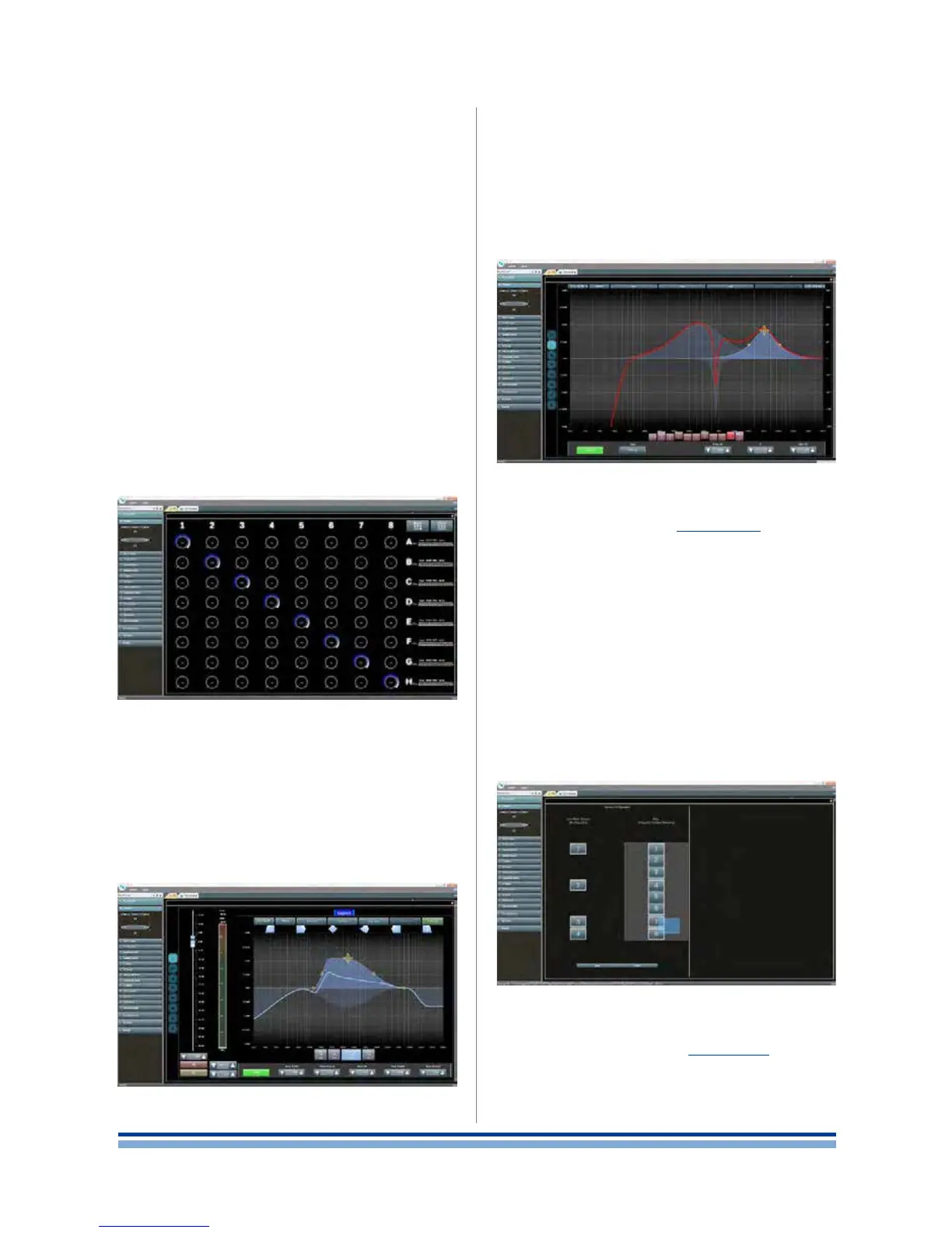
15 : 4.5. Speaker routing
The speaker routing stage (FIGURE 35 #6) aims to suit
the conguration of multi-way loudspeakers: once properly
grouped, the output channels are presented to the matrix
as speakers – a single row representing a speaker (actu-
ally group of ways) – allowing a high grade of granularity in
signal processing.
Routing of the signals entering the speaker routing stage
can be made only on adiacent output connectors, i.e. you
can choose to group the output channels 3 and 4, but you
can not group channel 3 and 5.
In order to group the output channels simply drag a
selection over the output channels on the right column
and press apply. The left column will show the label of the
speaker corresponding to the groups (loudspeakers) you
create.
15 : 4.6. Output processing
The output processing stage (FIGURE 35 #5) allows ne
tuning of output signals, aiming to optimize power delivering
and loudspeaker performance. It provides gain and polarity
adjustment, IIR and FIR full parametric lters, delay, mute,
limiting and damping control on each output channel.
FIGURE 38: Matrix.
FIGURE 37: Input processing.
FIGURE 39: Speaker equalization.
FIGURE 40: Speaker routing.