Installation
33
Powerware
®
9125 User’s Guide (2500–3000 VA) : Rev B www.powerware.com
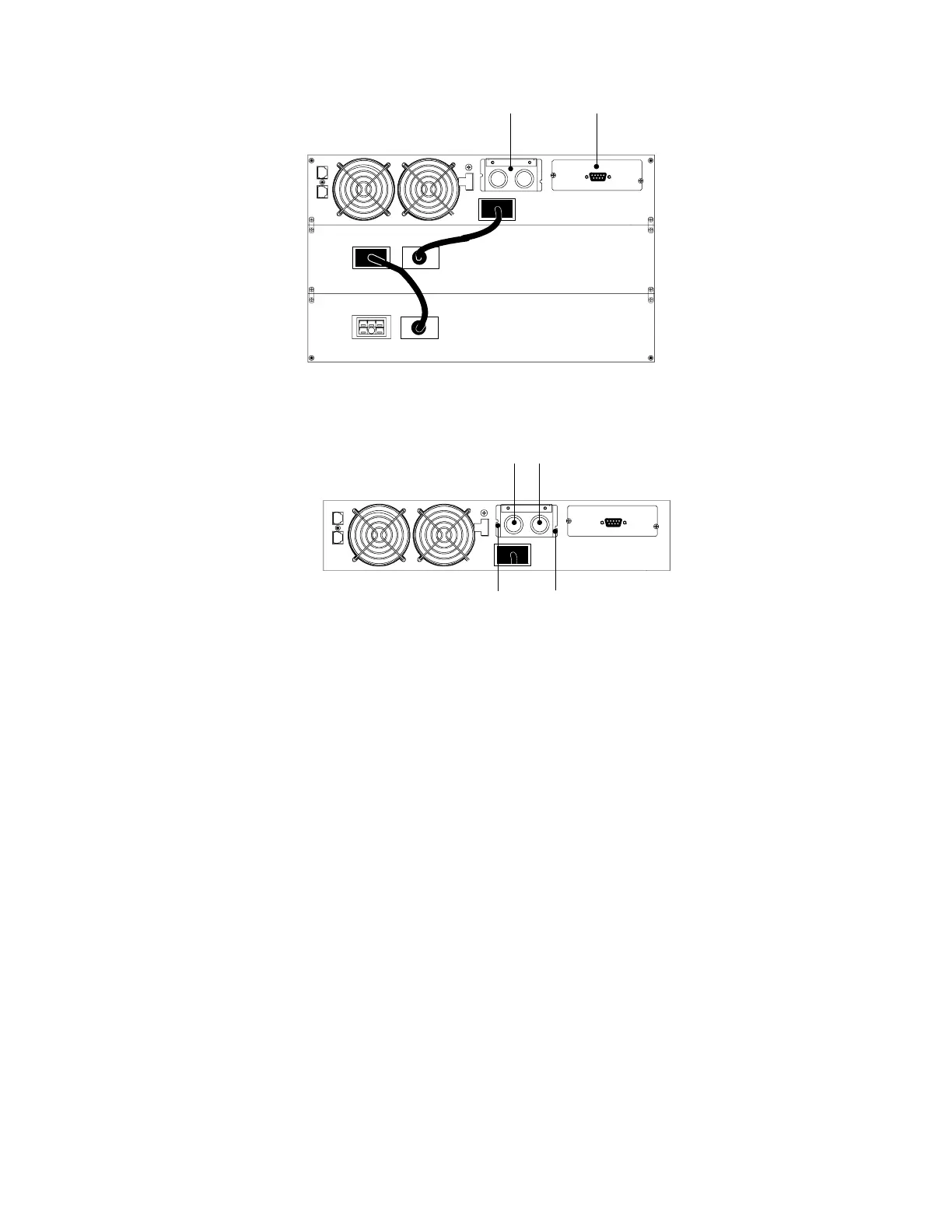
Communication PortTerminal Block Cover
Figure 17. Typical Hardwired UPS Installation
3. Remove the terminal block cover and the wiring knockouts (see
Figure 18). Retain the terminal block cover.
Input Wiring Access Output Wiring Access
Terminal Block Cover Screws
Figure 18. Wiring Access and Terminal Block
4. Pull the input and output wires through separate conduit,
leaving approximately 2 ft (0.5m) of exposed wire. Attach a
flexible metal fitting to the end of each conduit.
5. Insert each conduit through a wiring access entry and attach
the conduit fitting to the panel. Strip 0.5
2
(1.5 cm) of
insulation from the end of each incoming wire.