Installation
34
Powerware
®
9125 User’s Guide (2500–3000 VA) : Rev B www.powerware.com
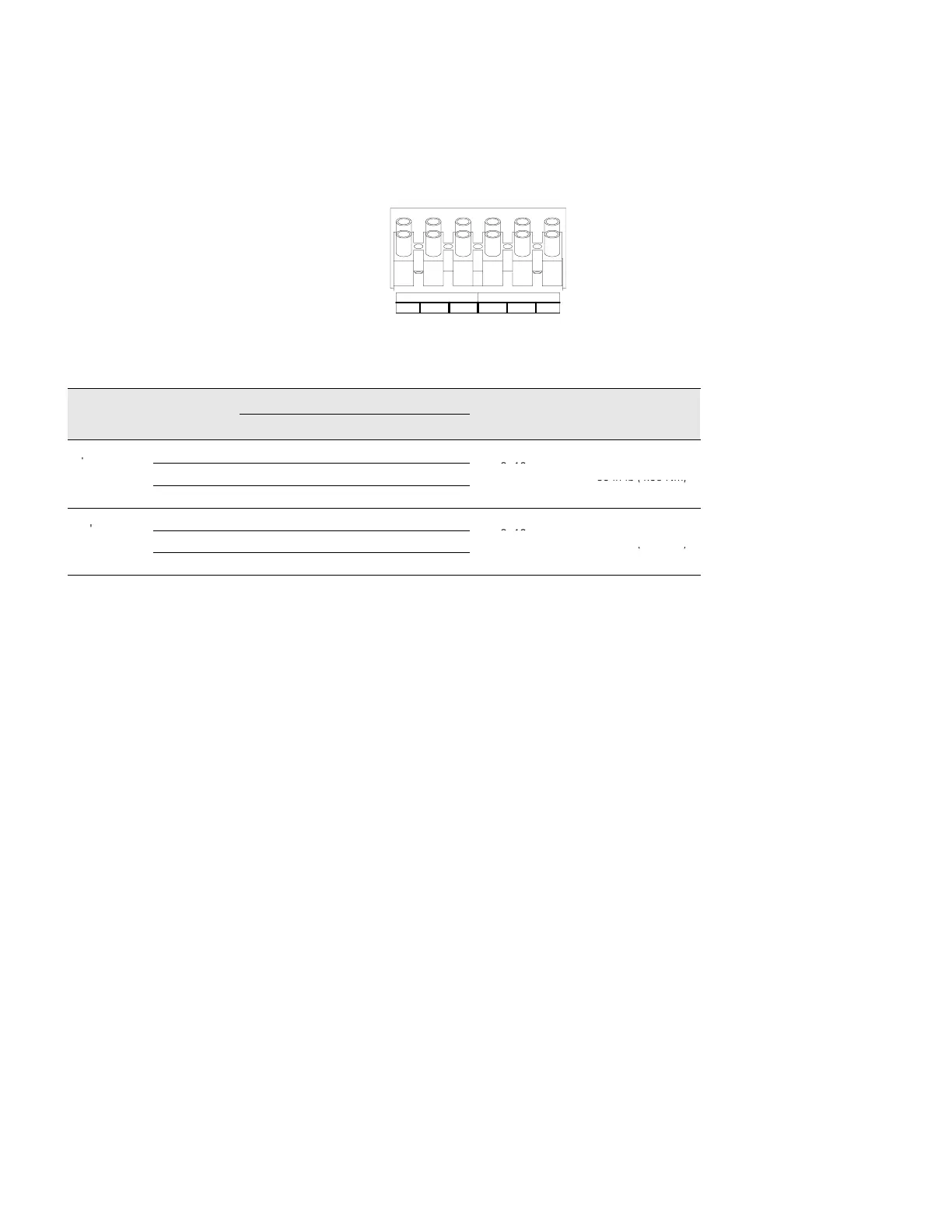
6. Connect the input and ground wires to the input terminal
block according to Figure 19 and Table 1.
7. Connect the output and ground wires to the output terminal
block according to Figure 19 and Table 1.
INPUT
13
OUTPUT
2465
Figure 19. Terminal Block
Table 1. UPS Wiring Specifications
Wire Terminal
UPS Wire Function
Terminal Wire Tightening
Function
Position
EUH Models EH Models
Size Rating*
Torque
Input
1 L2 N
2 G G
2–16 mm
2
–
35 in lb (4.38 Nm)
3
L1 L
–
Output
4 L2 N
5 G G
2–16 mm
2
–
35 in lb (4.38 Nm)
6
L1 L
–
*Use 2.0 mm
2
(14 AWG) 75EC copper wire minimum.
8. Replace the terminal block cover.
9. If an emergency power-off (disconnect) switch is required by
local codes, see “Remote Emergency Power-Off” on page 36 to
install the REPO switch before powering on the UPS.