The Primary and Secondary switches are engaged with a single actuator attached to the right-side
hinge. Because of this design, the door position has a direct and precise relationship with the switch
contacts.
The actuator is a part with a step machined into one side to allow for the Primary switch to open
before the Secondary switch (mounted beside it). This step is hardly noticeable due to its height of
0.01” (0.25mm)
The two switches share the same adjustment and mounting hardware, but do not share the same
actuator surface. The 0.001” step allows for the required timing separation.
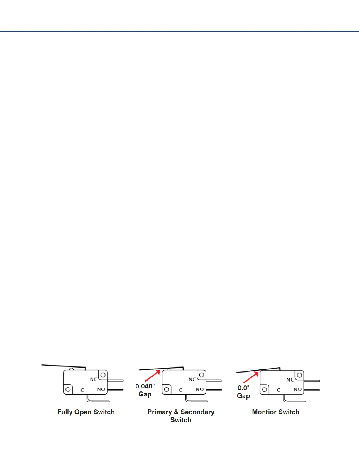
The proper distance to adjust the Primary and Secondary switches is 0.040” (1.0mm). This distance is
measured between the switch body and the metal paddle. At this distance, the opening sequence of
the three switches is correct and the microwave emission are well within the safety specifications.
The Monitor switch is located on the left side of the oven and is actuated per a round post with a step
machined into one side. The proper distance to adjust the Monitor switch is 0” (0mm). This switch is
to be adjusted fully closed to support the Primary and Secondary switch contacts opening first.
Primary and Secondary switch adjustment steps:
1) Open and close the door to verify the door moves freely and fully closes. The door springs
must be pulling the door closed to the oven cavity.
2) Remove both sides and the top cover top access the LED and the switches.
3) Loosen the #2 Phillips screw on the mounting bracket and the two #1 Phillips screws holding
the switch body.
4) Place a 0.040” (1.0mm) gauging tool between the switch body and the metal paddle.
5) Confirm the adjustment is correct and tighten mounting hardware.
6) Open and close the door while checking the sequence of de LED lights on the control board,
SW1 first, SW2 second, and SW3 is last to switch off when the door is opened.
7) Install a thread locking material to the mounting hardware (Optional).
Monitor switch adjustment steps:
Same as above with one exception: Change the dimension in step 4 above to 0” (0mm). This switch
must be fully closed when the door is in the closed position.