EFX 885, 835, 825
Service Manual 20039-166
Page 85
©2011 Precor Incorporated, Unauthorized Reproduction and Distribution Prohibited by Law
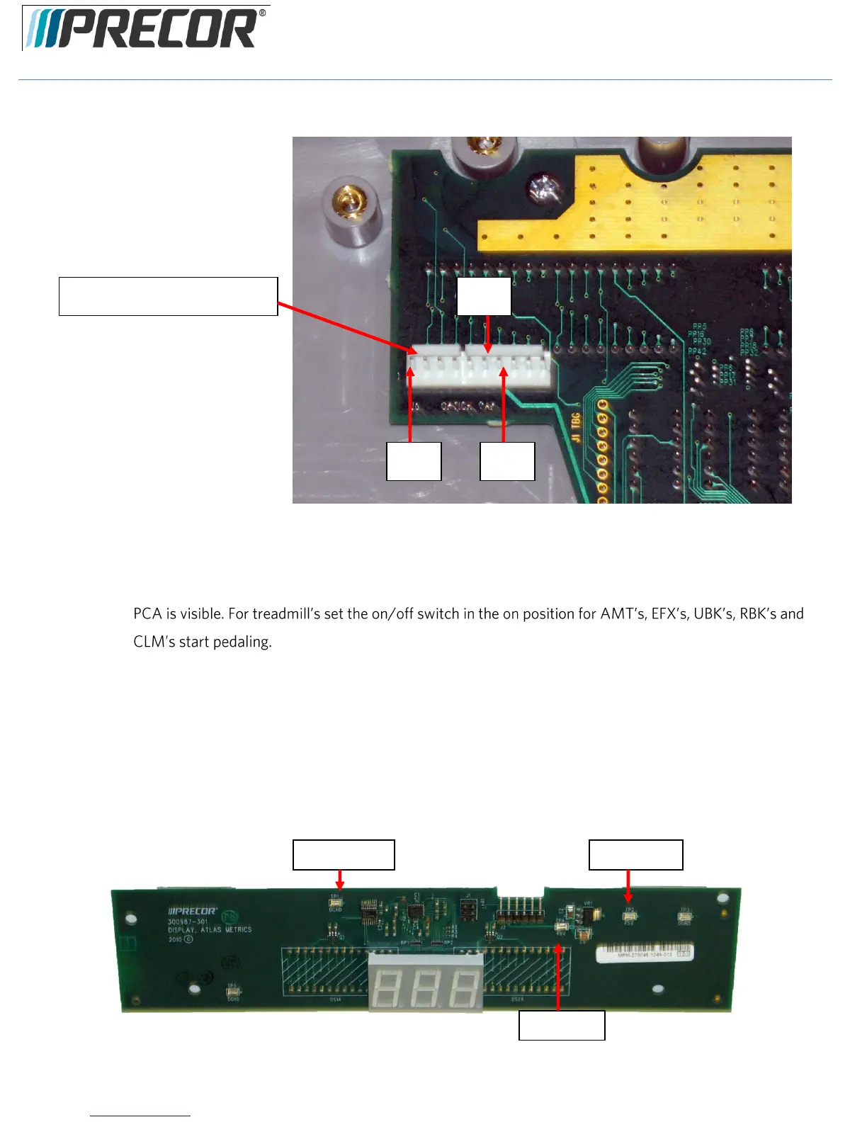
Diagram 5.11.2 - Console, Upper PCA , Option Cap (J6) Connector
5. If the upper PCA is not illuminating, skip to step 12.
6. If the metrics PCA is not illuminating, continue with step 7.
7. Remove the four screws that fasten the metrics PCA to the display face and rotate it so that the front of the
Note: There are four spacers between the Metric board and the mounting studs. These must be
saved and reinstall with the Metric board. If they are not used the Metric board or display face may
become damaged.
8. With a DC voltmeter, measure between TP4 (+8V) and TP1 (DGND) for 8 Vdc and between TP2 (+5V)
and TP1 (DGND) for 5Vdc. See Diagram 5.11.3
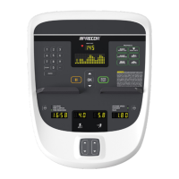
Diagram 5.11.3 - Metrics PCA, Front View
Option Cap (J6) Connector