Table of contents
Required equipment / tools / materials for installing a complete system _______________________ 3
Vehicle check ________________________________________________________________________ 3
General instructions __________________________________________________________________ 4
Introduction _________________________________________________________________________ 5
Approval numbers VSI LPG / CNG components ___________________________________________ 6
The Prins LPG reducer ________________________________________________________________ 7
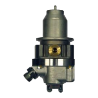
The Keihin CNG regulator ______________________________________________________________ 8
The injector rail ______________________________________________________________________ 9
The Prins filter unit __________________________________________________________________ 10
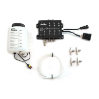
The Keihin filter unit _________________________________________________________________ 10
The VSI computer ____________________________________________________________________ 11
VSI-I _______________________________________________________________________________ 11
VSI-2.0 computer ____________________________________________________________________ 12
Instructions rotating the Prins VSI injector rail ___________________________________________ 13
The wiring loom. _____________________________________________________________________ 14
VSI-I _______________________________________________________________________________ 14
VSI-2.0 _____________________________________________________________________________ 14
Hose connections ___________________________________________________________________ 15
Diagram 1 VSI inlet manifold coupling _________________________________________________ 16
Diagram 2 VSI inlet manifold coupling with nylon hose __________________________________ 17
Diagram 3 Parallel water connection __________________________________________________ 18
Diagram 4 Serial water connection____________________________________________________ 19
Diagram 5 Serial water connection CNG regulator _______________________________________ 20
The VSI-I fuel switch _________________________________________________________________ 21
The VSI-2.0 fuel switch _______________________________________________________________ 22
Electrical connections on the LPG reservoir _____________________________________________ 23
Electrical connections VSI-I wiring harness ______________________________________________ 24
Electrical connections VSI-I wiring harness ______________________________________________ 25
Electrical connections VSI-2.0 wiring harness ____________________________________________ 26
Electrical connections VSI-2.0 wiring harness ____________________________________________ 27
Insulate all not used wires. ____________________________________________________________ 27
Electrical connections VSI-2.0 wiring harness ____________________________________________ 28
Electrical connections VSI-2.0 wiring harness ____________________________________________ 29
Electrical connections RPM module 091/0236 ____________________________________________ 30
Electrical connections Petrol Pressure Simulator 091/0252 _________________________________ 31
Electrical connections Dual Sensor Interface (DSI) ________________________________________ 32
Electrical connections CNG Prins Timing Optimizer (PTO) _________________________________ 33
Diagram CNG PTO wiring Prins Turbo / MAP sensor ______________________________________ 33
Prins Turbo / MAP sensor _____________________________________________________________ 34
Diagram 5 LPG Base layout VSI 4 cylinder connector ____________________________________ 35