EasyManua.ls Logo

Prins VSI LPG - Electrical Connections VSI-2.0 Wiring Harness

Prins VSI LPG
77 pages
Print Icon
To Next Page IconTo Next Page
To Previous Page IconTo Previous Page
Loading...
Copyright © Prins Autogassystemen B.V. 2013 Page 29
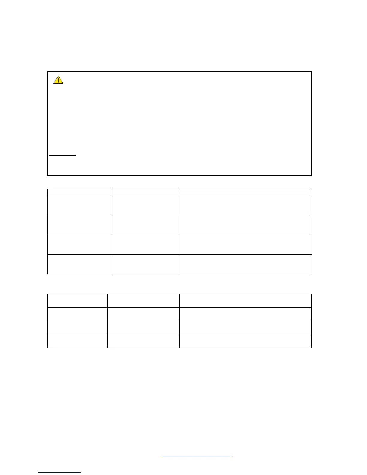
Electrical connections VSI-2.0 wiring harness
Check and measure the wiring in case of changes in the cars wiring colours.
For measuring the petrol injectors :
Interrupt each petrol injector control wire (injector min)
Each VSI wire has a petrol injector / cylinder number printed on the wire, connect this wire to the
corresponding petrol injector / cylinder.
Connect the bicoloured VSI measuring wire to the ecu side, ( wire code: ecu side inj ).
Connect the corresponding full coloured VSI wire to the petrol injector side ( wire code: min inj side ).
Attention:
Each bicoloured measuring wire corresponds to a specific VSI injector and petrol injector /
cylinder number. Do not interchange the wires.
VSI measure wire nr. :
Full coloured / Bicoloured
To interrupt petrol injector wire colour / location
121 ecu side injector 1
120 injector side inj 1
white-yellow
white
Colour :
Location :
119 ecu side injector 2
118 injector side inj 2
green-yellow
green
Colour :
Location :
117 ecu side injector 3
116 injector side inj 3
pink-yellow
pink
Colour :
Location :
115 ecu side injector 4
114 injector side inj 4
blue-yellow
blue
Colour :
Location :
VSI injector connectors:
98 GAS INJ 1
106 +GAS INJ 1
white-yellow
red
Connector VSI-injector cylinder 1.
( timing belt side )
99 GAS INJ 2
107 +GAS INJ 2
green-yellow
red
Connector VSI-injector cylinder 2.
100 GAS INJ 3
108 +GAS INJ 3
pink-yellow
red
Connector VSI-injector cylinder 3.
82 GAS INJ 4
90 +GAS INJ 4
blue-yellow
red
Connector VSI-injector cylinder 4.

Table of Contents

Related product manuals